Activated Sludge Process – Stages and Process Control

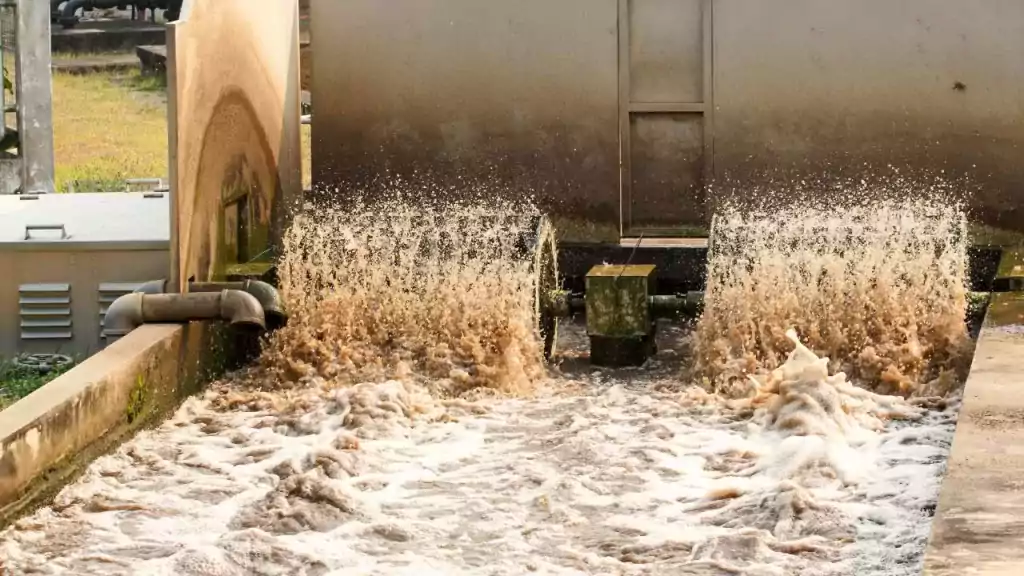
The activated sludge process is a widely used and highly effective method in wastewater treatment, employing aerobic microorganisms to remove organic pollutants efficiently. This guide covers the activated sludge process definition, stages, and diagram, while explaining its role in secondary wastewater treatment for producing high-quality effluent. You will understand how aeration tanks, wastewater treatment microorganisms, mixed liquor suspended solids (MLSS), and return activated sludge (RAS) work together to maintain stable and efficient system performance. The activated sludge process in wastewater treatment relies on proper aeration, controlled sludge recycling, and effective process monitoring. Due to its reliability, adaptability, and high treatment efficiency, activated sludge wastewater treatment remains the preferred choice for many municipal and industrial wastewater treatment plants, ensuring consistent performance and environmental compliance.

Activated Sludge Process is a globally used wastewater treatment technique. In the previous blogs, I had shown you the various secondary wastewater treatment techniques. In this blog, we will dig deep into this widely used technique of activated sludge process, its configuration, process control and aeration methods.

Activated sludge Process – Definition

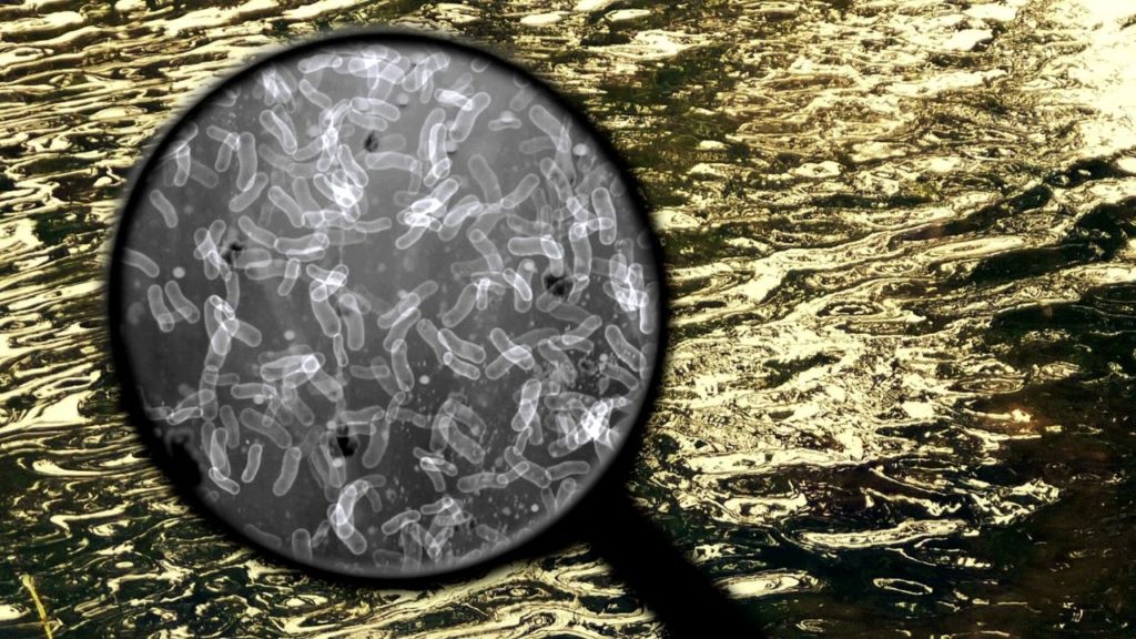
The activated sludge process is a type of wastewater treatment that uses aeration. It involves a biological floc made up of bacteria and protozoa to clean sewage or industrial waste waters. This process is biological and has various applications. It includes oxidising carbonaceous biological matter. Additionally, it deals with nitrogenous waste in the biological matter, mostly ammonium and nitrogen.

Before starting make sure that you take a quick glance through the blog, Wastewater Treatment- Stages and Process full details for better understanding

Aerial view of multiple circular wastewater treatment tanks with varying water clarity, surrounded by greenery.
Aerial view of multiple aeration tanks used in the activated sludge process for wastewater treatment.

The activated sludge process employs aerobic microorganisms that can digest organic substances in sewage. Also, they have the ability to cluster together via flocculation. The flocculated particles settle out as sludge. As a result, the liquid coming out is relatively free of suspended solids and organic matter.

Activated Sludge Process – Stages, Configuration, and Diagram

The activated sludge process is a widely used secondary wastewater treatment method. It removes carbonaceous organic pollution through aerobic biological activity. The configuration of an activated sludge wastewater treatment system consists of interconnected units that operate together to ensure efficient treatment.
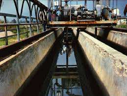
Aeration Tank

The aeration tank is the heart of the activated sludge process in wastewater treatment. Primary treated sewage is mixed with microorganisms, forming mixed liquor suspended solids (MLSS). Air or oxygen is supplied using diffusers or mechanical aerators to support aerobic microbes. These microorganisms consume organic matter and convert it into stable end products.

Secondary Settling Tank (Secondary Clarifier)

The mixed liquor flows into the secondary settling tank, where biological flocs settle by gravity. Clarified effluent overflows for further treatment or discharge. Settled sludge collects at the bottom.

Sludge Recycling System

A portion of the settled sludge is returned as Return Activated Sludge (RAS) to maintain microbial concentration in the aeration tank. Excess sludge is removed as Waste Activated Sludge (WAS) to control sludge age and system stability.

Advanced control systems regulate aeration, sludge recycling, and flow rates, ensuring stable and efficient secondary wastewater treatment performance.

Now, how about looking deep into what happens inside an activated sludge process?

Diagram illustrating the activated sludge process, featuring an aeration tank, mixed liquor, secondary clarifier, return activated sludge (RAS), and waste activated sludge (WAS).
Diagram illustrating the activated sludge process, featuring the aeration tank, secondary clarifier, mixed liquor, return activated sludge (RAS), and waste activated sludge (WAS) pathways.

Activated Sludge Process Steps

The activated sludge process operates through a series of well-defined stages that enable effective secondary wastewater treatment. Each stage supports biological activity, sludge separation, and recycling to achieve high organic pollutant removal and regulatory compliance.

  • After primary treatment, wastewater enters into an aeration tank. A portion of sludge from the secondary settling tank also enters.
  • Organic matter comes into close contact with sludge from the secondary settling tank. Sludge is densely populated with microorganisms that are actively growing.
  • Diffusers or surface aerators inject air in the form of bubbles into the sewage-sludge mixture.
  • Microorganisms break down organic matter into stable chemicals like NO3, SO4, and CO2 while also producing new bacterial cells.
  • The effluent along with the actively growing microbial population passes to the secondary settling tank.
  • The secondary settling tank separates the aeration tank’s effluent, which contains flocculent microbial matter into supernatant and sludge. The treated supernatant undergoes further treatment before discharge.
  • This sludge from the settled waste returns to the aeration system’s inlet to re-seed the new wastewater reaching the tank. Return activated sludge (R.A.S.) is the fraction of the floc that returns to aeration tank.
  • The remaining sludge goes to sludge digesters for further treatment and safe disposal.

“Mixed liquor” refers to the combination of the liquid and microorganisms in the aeration tank. The suspended solids are called “Mixed Liquor Suspended Solids” (MLSS).

In the next section, we will find out the basic process control parameters in an activated sludge process.

Close-up of foam and sediment in a wastewater treatment process, illustrating the activated sludge process used for organic pollutant removal.
Foamy surface of wastewater during the activated sludge process, illustrating the aeration and microbial activity involved in organic matter treatment.

Process Control in Activated Sludge Process

The general process control method monitors the following variables:

  • Sludge Volume Index (SVI)
  • Mean Cell Residence Time (MCRT)
  • Food to Microorganism Ratio (F/M)
  • Dissolved oxygen (DO)
  • Biochemical oxygen demand (BOD)
  • Chemical oxygen demand (COD)

Let me explain these parameters in detail.

Sludge Volume Index

Sludge Volume Index measures the volume of settled sludge in milliliters. This volume is occupied by 1g of dry sludge solids after 30 minutes of settling in a 1000 milliliter graduated cylinder. It gives a measure of the settling ability of the sludge. SVI ranges from 40 to 100 for a good sludge which settles down easily. Bulking Sludge is a biomass consisting of filamentous organisms with very poor settling characteristics. For a bulking sludge, SVI value can exceed 200. Sufficient pH control, adequate aeration and addition of hydrogen peroxide to the aeration tank prevents bulking.

Mean Cell Residence Time

Mean Cell Residence Time is the ratio of total mass (lbs) of mixed liquor suspended solids in the aerator and clarifier to the mass flow rate (lbs/day) of mixed liquor suspended solids leaving as final effluent.

Food to Microorganism Ratio

The Food to Microorganism Ratio indicates how much organic matter is fed to the microorganisms each day. It is relative to the mass of microorganisms under aeration. In other words, it is the ratio of the amount of BOD fed to the aerator (lbs/day). It is compared with the amount (lbs) of Mixed Liquor Volatile Suspended Solids (MLVSS) under aeration. 

Main Control Parameters

The mean cell residence time and F/M Ratio are the main control parameters used industrially. Both are directly related to the effluent quality. However, it is tedious to control the plant on the basis of the F/M ratio since it necessitates a lot of laboratory work to find the BOD and MLSS in the system. Therefore, the mean cell residence time is the best choice for controlling an activated sludge system.

Now you got an idea about the entire process and its important parameters. Next, we move on to the various aeration methods.

Aeration Methods in Activated Sludge Process

The decomposition of organic waste requires a very high concentration of oxygen at the initial stages of contact between microorganisms and the organic matter. The conventional systems usually maintain a plug flow hydraulic regime and keeps aeration and a mixing at an uniform rate along the entire tank. As a result, the oxygen concentration drops rapidly in the inlet and this can harm the microbes.

At the outlet, there is a surplus of oxygen which is not necessary and leads to economical losses. In order to match the oxygen supply and demand along the entire journey of wastewater from inlet to outlet, the mode of aeration needs some modifications. Let’s have a look at the different aeration methods in an activated sludge process.
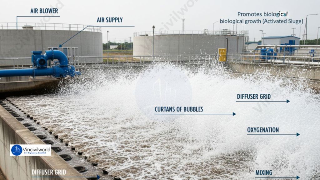
Diffused Aeration

Sewage liquor is pumped into large tanks with floor-mounted diffuser grid aeration devices. Passing air creates a curtain of bubbles that oxygenates the liquor while also mixing it. An air blower usually creates the air. Oxygen replaces air for unusually strong and difficult to treat sewage.

Aeration tank in activated sludge process featuring air supply and diffuser grid for oxygenation, promoting biological growth with visible bubbles.
Diffused aeration system in activated sludge process, promoting oxygenation and biological growth.

Tapered Aeration

The organic waste needs more oxygen at the inlet. As it degrades progressively its oxygen demand decreases. Tapered aeration works on this principle. Aeration is intense at the inlet and decreases progressively along the length of the aeration tank. As this method involves the more efficient use of air, it results in savings in the pumping costs too.

Step Aeration

This method aims to equalize the oxygen supply and its demand. It introduces fresh feed at several points in the aeration tank, while keeping the rate of oxygen supply constant. This ensures a more even oxygen distribution over the entire tank and throughout the aeration stage. Baffles divide the aeration tank into several channels with each channel representing one step of the process.

Complete Mix Activated Sludge Process

In complete mix process, the aeration tank receives a mixture of fresh feed and recycled sludge at several locations within the tank. This ensures a constant supply and demand of oxygen along the length of the tank.

Contact Stabilisation

The microbial mass comes in contact with wastewater for short durations of time, approximately 0.5 to 1 hour in the biosorption unit. An anaerobic digestion unit stabilizes the resulting sludge after a retention period of about 2-3 hours. In the digestion unit, microbes consume the organic wastes removed in the biosorption unit. Since we stabilize the return sludge with higher solid concentrations, this reduces the volume of the aeration tank.

Pure Oxygen Activated Sludge Process

This type of activated sludge process supplies pure oxygen instead of air. It recirculates this oxygen into well mixed and converted chambers. Conventional processes utilize only 5-10% of oxygen. In contrast, the pure oxygen activated sludge process ensures about 90% utilization of oxygen. Further, it results in higher bacterial activity, lower sludge volume and sludge with better settling characteristics.

That’s it about activated sludge process. Let us know in the comments if you wish to know more.

Key Takeaways

  • The activated sludge process effectively treats wastewater using aerobic microorganisms to remove organic pollutants.
  • Key stages include aeration tanks, secondary settling tanks, and sludge recycling to maintain treatment efficiency.
  • Proper aeration and control parameters like SVI and F/M Ratio are essential for optimal performance.
  • Various aeration methods, such as diffused and tapered aeration, improve oxygen supply and microbial activity.
  • This process provides a reliable solution for secondary wastewater treatment, ensuring cleaner effluent.

Conclusion

The activated sludge process is a proven method for secondary wastewater treatment. It is highly efficient and used worldwide. This process removes organic pollutants from sewage and industrial wastewater. This process promotes aerobic microbial activity in aeration tanks. It achieves effective BOD reduction, suspended solids removal, and stable effluent quality. Proper control of operational parameters, such as dissolved oxygen, MLSS, and sludge age, ensures consistent system performance. It also prevents common issues like sludge bulking. With multiple activated sludge process configurations and aeration methods, the system can adapt to varying wastewater loads and treatment requirements. Due to its flexibility, reliability, and high treatment efficiency, the activated sludge process remains a cornerstone of modern biological wastewater treatment systems and sustainable water management.

Eutrophication – Definition, Causes, Effects and Control

Eutrophication is a natural process in water bodies that becomes problematic when accelerated by human activities. It is caused by the excessive accumulation of nutrients, particularly nitrogen and phosphorus, leading to algal blooms and oxygen depletion. This phenomenon, also known as cultural eutrophication, occurs when agricultural runoff, wastewater discharge, and industrial effluents introduce pollutants into water systems. The cause of eutrophication is primarily linked to nutrient overloading, which fosters the growth of algae, eventually causing harm to aquatic ecosystems. The process of eutrophication disrupts aquatic life, while its effects include loss of biodiversity, poor water quality, and fish mortality. Understanding eutrophication causes and effects is crucial for managing its impact. In simple terms, eutrophication explained involves the imbalance caused by excess nutrients in aquatic systems.

Eutrophication in US freshwaters costs approximately $2.2 billion per year. Astonishing, right? Want to know more about this process that can wreak havoc if left unchecked? In this blog, let’s visit a eutrophied lake and understand the entire events that lead to eutrophication and its effects.

Let’s dive in.

  1. What Is Eutrophication?
  2. Eutrophication Process
  3. Types of Eutrophication
    1. Natural Eutrophication
    2. Cultural Eutrophication
  4. Eutrophication Effects
    1. Loss of Biodiversity
    2. Harmful Algal Blooms (HABs)
    3. Monetary Loss
  5. Eutrophication Control Measures
  6. Key Takeaways
  7. Conclusion

What Is Eutrophication?

Eutrophication refers to the process of nutrient over-enrichment in water bodies. It involves primarily nitrogen and phosphorus. This leads to excessive algal and plankton growth. This phenomenon, often termed cultural eutrophication, occurs due to human activities such as agricultural runoff and fertilizer use. Eutrophication explained highlights that this process reduces dissolved oxygen levels, causing poor water quality and threatening aquatic ecosystems.

The cause of eutrophication is primarily linked to artificial fertilizers and untreated waste discharge. As algae bloom, oxygen depletion follows, creating “dead zones” incapable of supporting life. This causes both environmental and ecological harm, ranking alongside global warming and deforestation. Understanding eutrophication meaning involves addressing the causes of eutrophication like synthetic fertilizers and urban runoff. The effects of eutrophication include biodiversity loss and water quality degradation, making it a critical issue in environmental management.

Also check out : Wastewater Treatment- Stages and Process full details.

In the next section, I will show you how a water body undergoes eutrophication.

Eutrophication Process

  • Soil receives nutrients in excess from synthetic fertilizers. Surface runoff washes them away into the water body.
  • Nutrients reach the water body via untreated sewage and industrial effluents too.
  • Excess nutrients cause accelerated growth of algae or algal bloom.
  • Light penetration reduces due to the algal bloom.
  • Plants beneath the algal bloom perish because they are unable to perform photosynthesis in the absence of sunshine.
  • The algal bloom eventually dies and settles to the lake’s bottom.
  • Bacterial populations begin to break down the remnants, consuming oxygen in the process.
  • Oxygen is lost in the water as a result of decomposition.
  • Aquatic organisms die due to a lack of dissolved oxygen. The waterbody turns into a dead zone which doesn’t support life.
Eutrophication Process

Types of Eutrophication

Based on the source of nutrient enrichment, there are two types of eutrophication. They are:

Natural Eutrophication

Although human activities are the most prevalent cause of eutrophication, it can also be a natural process, especially in lakes. Due to climate change, geology and other external factors, the nutrient density of a water body increases over time and undergoes the process of natural eutrophication.

A few lakes also show the reverse process called meiotrophication. In this process, nutrient-poor inputs make the lake less nutrient-rich over time. Artificial lakes and reservoirs usually undergo this process, which starts out as very eutrophic but eventually become oligotrophic. An oligotrophic lake is a lake with low primary productivity due to low nutrient content.

The major difference between natural and anthropogenic eutrophication lies in the timescale. The former takes geologic ages to complete while the latter is a quick process.

Cultural Eutrophication

Eutrophication caused by human activity is also known as cultural or anthropogenic eutrophication. It is a process that accelerates natural eutrophication. Land runoff increases as a result of the land clearing and construction of towns and cities. Therefore, surface runoff from croplands carry nutrients such as phosphates and nitrate into the lakes and rivers, and then to coastal estuaries and bays.

When excess nutrients from anthropogenic sources such as runoff from fertilised croplands, lawns, and golf courses, untreated sewage and wastewater end up in water bodies, they cause nutrient pollution and simultaneously speeds up the natural process of eutrophication. The degradation of water quality induced by cultural eutrophication severely impacts human uses such as potable water, industrial usage, and recreation.

Let’s move on to the section describing its effects or consequences.

Eutrophication Effects

The effects of eutrophication range from ecological losses to economical losses. Let’s have a closer look at each one of them.

Loss of Biodiversity

Aquatic environments support a diverse range of plant and animal life. The process of eutrophication disrupts the ecosystem’s balance by promoting the growth of basic plant life. The ecosystem’s biodiversity is drastically reduced as a result of the loss of some desirable species.

The most noticeable consequence of cultural eutrophication is the formation of dense blooms of toxic, foul-smelling blue-green algae or cyanobacteria that impairs water clarity and quality. Algal blooms reduce light penetration. This limits aquatic plant growth and diminishes the success of predators that rely on light to hunt and catch prey in the benthic zone. Eventually, it leads to the mass death of aquatic plants and organisms.

Furthermore, eutrophication’s high rates of photosynthesis drain dissolved inorganic carbon and elevate pH to dangerously high levels throughout the day. By diminishing chemosensory skills, elevated pH can ‘blind’ organisms that use the sense of dissolved chemical cues for survival.

When the dense algal blooms die, microbial breakdown depletes dissolved oxygen, resulting in a hypoxic or anoxic “dead zone” where most species are unable to survive. Many freshwater lakes contain dead zones. Eutrophication-induced hypoxia (extremely low oxygen concentrations in bottom waters) and anoxia pose a danger to profitable commercial and recreational fisheries around the world.

Eutrophication effects

Harmful Algal Blooms (HABs)

Some algal blooms are also dangerous because they produce toxins like microcystin and anatoxin-a. Harmful algal blooms (HABs) leads to:

  • water quality degradation
  • the extinction of commercially important fishes 
  • public health problems 

Toxic cyanobacteria such as Anabaena, Cylindrospermopsis, Microcystis, and Oscillatoria (Planktothrix) dominate nutrient-rich, freshwater systems due to their superior competitive abilities under high nutrient concentrations, low nitrogen-to-phosphorus ratios, low light levels, reduced mixing, and high temperatures.

Algal Blooms
Algal Blooms

Toxic cyanobacteria bloom causes poisonings of domestic animals, wildlife, and even humans all around the world. For instance, shellfish poisoning is a result of HABs. Shellfish ingests the biotoxins produced during algal blooms. When humans consume them, it leads to various kinds of poisoning including paralytic, neurotoxic, and diarrhoetic shellfish poisoning.

Ciguatera, a predator fish becomes a vector for such toxins by accumulating the poison in its body and then poisoning the humans who consume it. Furthermore, cyanobacteria are responsible for various off-flavour compounds (such as methyl isoborneol and geosmin) detected in municipal drinking water systems.

Monetary Loss

Due to the continuous feeding of the fish, aquaculture ponds often accumulate high concentrations of nutrients such as nitrogen and phosphorus. As a result, these ponds are subjected to cyanobacterial blooms and hypoxia regularly. aquaculture-reared fish, resulting in significant financial losses.

Eutrophication also lowers the recreational value of rivers, lakes, and beaches. This severely impacts the tourism sector. When eutrophic conditions interfere with the treatment of drinking water, health concerns and monetary losses arise.

OK, I know what you’re thinking. How to control eutrophication, right? Read on to find more.

Eutrophication Control Measures

  • Prevent the flow of plant nutrients to water bodies. Reduce the overuse of synthetic fertilizers.
  • Proper channelling of agricultural wastes and runoffs.
  • Releasing only safe and treated effluents to water bodies.
  • Seaweed cultivation absorbs nitrogen and phosphorous and removes excess nutrients.
  • Promoting the growth of shellfish.

That’s it about eutrophication. Hope you found it useful.

Key Takeaways

Eutrophication is a nutrient enrichment process in water bodies, primarily caused by nitrogen and phosphorus. While natural eutrophication takes centuries, cultural eutrophication accelerates due to human activities like agricultural runoff and untreated wastewater. This leads to algal blooms, oxygen depletion, and the formation of hypoxic or “dead zones,” harming aquatic ecosystems. Key effects include biodiversity loss, harmful algal blooms (HABs), water quality degradation, and economic losses in fisheries and recreation. Addressing eutrophication requires reducing nutrient pollution from fertilizers and industrial effluents. Understanding this process and its impacts is crucial for effective environmental management.

Conclusion

Eutrophication, whether natural or cultural, poses significant ecological and economic challenges. Cultural eutrophication, driven by human activities, intensifies nutrient pollution, causing harmful algal blooms and oxygen-depleted waters. The resulting biodiversity loss and water quality degradation lead to habitat destruction and economic losses, such as reduced fisheries and recreational opportunities. Combating eutrophication demands action, including limiting nutrient runoff, improving wastewater treatment, and promoting sustainable agricultural practices. By addressing these causes, we can mitigate the adverse effects on aquatic ecosystems and preserve water resources. Understanding eutrophication is key to safeguarding our environment and ensuring long-term ecological balance.

Sheet pile -Sheet piling types, sheet piling advantages

Sheet piles are essential components in construction and civil engineering. They are used in various applications, including retaining walls and foundations. The process of sheet piling involves driving long, vertical sections of sheet piles into the ground. This technique is crucial for creating a stable sheet pile foundation. There are different types of sheet piling, each designed for specific conditions and uses. Shore piling is another method related to sheet piling, primarily used for waterfront construction. To achieve successful project outcomes, it is important to understand sheet piling work. Familiarity with the types of sheet piling available is also beneficial in various construction scenarios.

In this article, we will explore the various types of sheet piling and their applications in construction. We will discuss the installation process of sheet piling work and the advantages of using a sheet pile foundation. Additionally, we’ll cover shore piling and how these techniques contribute to structural stability and safety in diverse projects.

  1. What is a sheet pile ?
  2. Sheet piling method
  3. Sheet piles – Applications
    1. Retaining walls
    2. Coastal protection:
    3. Cofferdams
    4. Underground structures
  4. Advantages of sheet pile
  5. Sheet piling types
    1. Steel Sheet piles
    2. Vinyl sheet pile
    3. Wooden sheet pile
    4. Features of wooden piles
    5. Concrete sheet pile
    6. Aluminium sheet piles
    7. Composite sheet piles
    8. Cellular sheet pile
    9. Cold-formed sheet piles
  6. Conclusion

What is a sheet pile ?

A sheet pile is a type of driven pile that uses sections of sheet materials with interlocking edges. We generally install Sheet piles for lateral earth retention, excavation support, and shoreline protection operations. They are typically made of steel, but can also be made of vinyl, wood, or aluminum. Sheet piles are installed in sequence to the design depth along the excavation perimeter or seawall alignment. The interlocking sheet piles provide a wall for permanent or temporary lateral earth support with little groundwater inflow. We use Anchors strategically to provide lateral support Anchors.

We frequently use Sheet piles for seawalls, retaining walls, land reclamation, and underground constructions. Underground constructions include parking garages, and basements, in marine locations for riverbank protection, seawalls, cofferdams, and so on.

Sheet piling method

Sheet piles can be temporary or permanent. Permanent steel sheet pile design demands a long service life. Often we install Sheet piles using vibratory hammers. If the earth is too hard or dense, we perform the installation with an impact hammer. Hot-rolling and cold-forming are the two major methods for creating sheet piles. Manufacturing of Hot rolled piles takes place at high temperatures, and the interlocks appear to be stronger and more durable.

Sheet piles are installed by driving them into the ground with an impact hammer or vibratory driver. We connect them to one another by using a number of interlocking mechanisms. This includes tongue-and-groove, hook-and-grip, and clutch-bolt connections. Sheet piles, once erected, form a continuous barrier. This barrier resists lateral pressure from soil or water. It prevents soil erosion, landslides, and other soil failures.

sheet piles
Sheet piling

Sheet piles – Applications

Piles find frequent utilization in the following construction projects:

Retaining walls

Sheet piles help to construct retaining walls that hold back soil or water while also providing lateral support for excavations.

Coastal protection:

Sheet piling can protect coastal areas from erosion, waves, and storm surges. They can also be used to construct breakwaters and jetties.

Cofferdams

Sheet piles are used to build cofferdams. These are transient obstructions in water. They facilitate the construction of piers, bridges, or other water-based constructions.

Underground structures

We use Sheet piles to construct underground constructions such as basements or underground parking garages. They support the lateral structure and restrict soil or water intrusion.

Sheet piles have various advantages, including their versatility, ease of installation, and durability. Moreover, they offer an affordable option for projects that need lateral earth support. However, adequate design and installation are essential for guaranteeing the sheet pile wall’s stability and safety.

Advantages of sheet pile

Sheet piles provide several advantages in construction projects that require lateral earth support. Following are some of the key benefits of sheet piles:

  1. Versatility: Sheet piles find applications in a variety of construction projects, including retaining walls, shoreline protection, cofferdams, and underground structures.
  2. Speed of installation: Sheet piles are installed quickly and efficiently. We use impact hammers or vibratory drivers for this. These methods can reduce project timelines and construction costs.
  3. Durability: Sheet piles are made from steel or other durable materials. They can withstand harsh environmental conditions, including exposure to water, corrosion, and extreme temperatures. This makes them highly durable.
  4. Cost-effectiveness: Sheet piles generally prove to be a more affordable alternative to other types of foundation systems. They are ideal for projects requiring lateral earth support since they need less excavation and backfilling.
  5. Minimal disturbance: Sheet pile installation creates minimal disturbance to the surrounding soil and structures. We drive the piles into the ground without the need for excavation or other site preparation.
  6. Reusability: Sheet piles offer easy removal and reuse in other projects, making them a sustainable and Eco-friendly alternative.
  7. We use sheet piles for temporary and permanent structures. They are available in a wide range of lengths, sizes, and steel options.
  8. We can install Sheet piles rapidly using silent and vibration-free methods. The installation is easier and faster than secant walls.
  9. We can construct Cofferdams in almost any desired shape. Provide a close-fitting joint to form an effective water seal. Joints are designed to withstand the high pressure necessary for them to be placed in place. A little maintenance is needed above and underwater
sheet piling
sheet piling

Sheet piling types

Sheet piles are broadly classified as follows based on the material used for driving.

  • Steel sheet pile
  • Vinyl sheet pile
  • Wooden sheet pile
  • Concrete sheet pile
  • Composite sheet piles
  • Cellular sheet pile
  • Cellular sheet pile
  • Cold-formed sheet pile

Steel Sheet piles

Steel sheet piles are long and thin sections of steel. They are driven into the ground to construct a retaining wall or a barrier. Steel is the most popular material for sheet piles. We can lengthen it either by welding or bolting. Steel has great water tightness and good resistance to severe driving stresses. They find extensive applications in civil engineering and construction projects. These applications include providing structural support for excavations, bridges, highways, and other structures.

Steel sheet piles are primarily made of hot-rolled steel and are available in a variety of shapes and sizes. We can link them together to form a continuous wall. This wall acts as a strong barrier against the soil or water pressure. Steel sheet piles should endure heavy loads and give structural stability. Corrosion prevention techniques including coating and cathodic protection help increase the durability of steel sheet pile.

Steel sheet pile
Steel sheet pile

We frequently use Steel sheet piles in foundation work and deep excavations. They offer high resistance to lateral stresses. They also enable quick and simple installation. They are an Eco-friendly option for temporary constructions because we can recycle them.

Overall, steel sheet piles are a versatile and cost-effective solution for a wide range of civil engineering and construction projects.

There are four basic forms of steel sheet piles, Normal sections, Straight web sections, Box sections and Composite sections.

Vinyl sheet pile

A vinyl sheet pile is a form of plastic sheet pile. It finds applications in civil engineering and construction projects. These applications include seawalls, bulkheads, flood walls, and retaining walls. Vinyl sheet pile is primarily made of polyvinyl chloride (PVC). PVC is a lightweight and long-lasting polymer. It is resistant to corrosion, chemicals, and weathering. Vinyl sheet pile is becoming more common in construction projects. This is due to its minimal maintenance requirements. Its simplicity of installation and long-term durability also contribute to its popularity. Vinyl sheet pile does not require frequent maintenance or coating. Unlike traditional materials such as wood, steel, or concrete, this makes it a more cost-effective alternative in the long run.

Vinyl sheet pile is also environmentally friendly because it is reusable and does not leak dangerous chemicals into the soil or water. Because of its lightweight qualities, it is simple to transport and install, necessitating minimal use of heavy machinery and labour. Overall, vinyl sheet pile is a versatile and cost-effective solution for a variety of construction and civil engineering projects. Its durability, low maintenance requirements, and environmental benefits make it an appealing choice for contractors and engineers.

Vinyl Sheet Pile
Vinyl Sheet Pile

An effective alternative to steel sheet piling for bulkheads, seawalls and cutoff walls. They are also superior to alternative materials like concrete and wood. The main advantage of vinyl sheet piles is the superior corrosion resistance when exposed to seawater, where no oxidation occurs.

Vinyl sheet piles are lightweight and resistant to corrosion and chemical damage. They are often used in projects where environmental impact is a concern.

Wooden sheet pile

A wooden sheet pile is a type of retaining system comprising timber planks or boards. We commonly employ them in construction and civil engineering projects with a requirement for a retaining wall, either temporary or permanent. Hardwood sheet piles are a more environmentally friendly and long-lasting alternative to steel or concrete sheet piles. and they are widely utilised in places where environmental impact is a concern. In excavation work, we utilise them for braced sheeting and temporary structures. It must have some sort of preservative treatment for its utilisation in permanent structures above the water table. Even after treatment with a preservative, a timber sheet pile has limited life. Timber sheet piles are bonded using tongue and groove connections.

Features of wooden piles

Timber piles are not suitable in strata that contain gravel and boulders. Hardwood sheet piles are ideal for shallow excavations and we frequently utilise them in building projects where noise and vibration are a concern. They are lightweight and easy to handle, making them a popular choice for jobs requiring speedy installation. In comparison to other retaining wall materials, wooden sheet piles are also more affordable. Yet, there are significant drawbacks to using hardwood sheet piles. They are not as robust as steel or concrete sheet piles and require frequent maintenance to prevent rot and insect infestation. They may also be prone to warping and deformation if exposed to dampness for a lengthy period of time.

Hardwood sheet piles may not be suited for usage in places with high water tables or salinity in the soil, as these variables might accelerate the decomposition of the timber. Overall, hardwood sheet piles are an efficient and environmentally friendly option for small-scale building projects and temporary retaining walls. Yet, their durability and susceptibility to deterioration and warping make them unsuitable for long-term or large-scale applications.

wooden sheet piling
Wooden sheet pile

Concrete sheet pile

Concrete sheet piles are retaining walls constructed from precast reinforced concrete sections. We frequently employ them in civil engineering and building projects with a requirement for long-term retaining structures.

We must handle and drive the piles carefully, and provide the necessary reinforcement. The most common application of Concrete sheet pile occurs in deep excavations. These situations arise where soil conditions are unfavourable. In these cases, we require lateral support. They are impermeable and can withstand hydrostatic pressure, making them excellent for usage in places with high water tables. We provide a capping to the heads of the piles by casting a capping beam, while we cut the toes with an oblique face to make driving and interlocking easier. They are relatively heavy and thick, and while driving, they displace significant amounts of the earth.

The driving resistance rises as a result of the considerable volume displacement. Concrete sheet piles are also resistant to weathering, corrosion, and erosion, making them a durable solution under extreme conditions. Concrete sheet piles are available in a range of dimensions and we can interlock them to create a continuous wall. We can place them in a variety of ways, including driving, vibrating, and pushing. The method of installation depends on the accessibility to the site, the depth of the installation, the state of the soil etc.

concrete sheet piling
Concrete Sheet Pile
Concrete Sheet Pile

Concrete sheet piles are a strong and long-lasting alternative. However, their installation may be more costly and time-consuming than that of other retaining wall materials. However, installing them requires large machinery, which can be difficult in places with restricted access or space. Overall, concrete sheet piles are a viable option for permanent retaining walls in deep excavations and severe soil conditions. They are a preferred option due to their strength. They also have resistance to water and erosion, making them ideal for projects involving coastal protection and flood control.

Aluminium sheet piles

Aluminium sheet piles are lightweight, strong, and corrosion-resistant. They are an ideal choice for projects that require a lightweight and durable material.

aluminium sheet pile
Aluminium Sheet pile

Composite sheet piles

We manufacture Composite sheet piles from a combination of materials. These include steel and concrete. This combination provides additional strength and durability. They often find applications in projects that require high load-bearing capacity.

Cellular sheet pile

We usually design Cellular sheet pile with hollow sections that allow for increased strength and load-bearing capacity. They find application in projects that requires a high degree of lateral support.

Cold-formed sheet piles

Cold-formed sheet piles are made by bending steel sheets into a desired shape. They find application in projects requiring lower strength and load-bearing capacity.

Conclusion

Each type of sheet pile has its own advantages and disadvantages. The choice of material and design will depend on the specific requirements of the project. Proper design and installation are essential to ensure the stability and safety of the sheet pile wall. You should consult with an experienced engineer before selecting a specific type of sheet pile for a project

Types of beams – Top beam types explained

Types of beams popularly used In construction and engineering are classified based on their shape, the way they are supported, their structural behaviour etc. The beam is a horizontal or sloping structural member that supports a load and resists bending.In construction, beams are essential components that support loads and provide structural stability. This article explores the types of beams used in various applications, focusing on types of beam in building construction.We’ll cover what are the 4 types of beams, which are widely used in both residential and commercial projects. Additionally, we’ll discuss types of beams and support systems to understand how these beams interact with other structural elements. We’ll also examine different types of beams and their specific characteristics, along with popular beam types in modern construction. By the end, you’ll have a clear understanding of various type beams and their practical uses.

Beams are typically made from materials such as wood, steel, or concrete. They support floors, roofs, and walls. They also bridge gaps between supports. The type of beam used depends on factors such as the load to be supported, the span length, and the structural design of the building or structure. Beams can come in a variety of shapes, including rectangular, square, circular, and I-shaped. Proper selection and installation of beams are critical for ensuring the stability, safety, and durability of a structure.

This article is about the different types of beams popularly used in civil engineering and construction.

  1. Classification of beam types
    1. Types of beams based on the shape
      1. Rectangular beam
      2. Square beam
      3. Circular beam
      4. I-shaped (H-beam)
      5. T-shaped beam
      6. L-shaped beam
  2. Types of beams based on support conditions
    1. Simply supported beams
    2. Fixed beams
    3. Cantilever beams
    4. Continuous beams
    5. Overhanging beam
  3. Types of beams based on structural behaviour
  4. Types of beams based on materials used
    1. Timber beam
    2. Steel beam
    3. Concrete beam
    4. Composite beam
  5. Key Takeaways
  6. Conclusion

Classification of beam types

Types of Beams can be classified based on several factors, including their shape, the way they are supported, and their structural behaviour. Here are some common classifications of beams.

Beams are vital components in construction, and understanding the different types of beams is essential for choosing the right structure. So, what are the 4 types of beams? Beams can be categorized in various ways. Beam types based on shape include rectangular, I-beams, and T-beams. Type beams are also defined by their support conditions, such as simply supported and cantilever beams. What are the 4 types of beams based on structural behavior? These include flexural, axial, shear, and torsional beams. Additionally, the types of beams in building construction are often selected by material, including concrete, steel, and wood beams. Understanding the types of beams and support ensures optimal performance in construction.

Related posts from vincivilworld

  • Types of beams Based on the shape

Beams can be classified as rectangular, square, circular, I-shaped (also known as H-beam), T-shaped, and L-shaped.

  • Types of beams Based on support conditions

Beams can be classified as simply supported, fixed, cantilever, continuous, and overhanging.

  • Types of beams Based on structural behaviour

Beams can be classified as determinate or indeterminate. Determinate beams have a fixed number of supports and can be analysed using statics. Indeterminate beams have more supports than are needed for stability and require more advanced analysis techniques to determine their behaviour.

  • Types of beams Based on the material

Beams can also be classified based on the material used, such as wood, steel, or concrete.

The choice of beam type depends on the load to be supported, the span length, and the structural design of the building or structure.

Types of beams based on the shape

Beams can be classified based on their shape, which refers to the cross-sectional profile of the beam. The shape of the beam affects its structural properties, such as its strength, stiffness, and weight. Here are some common shapes of beams.

Rectangular beam

A rectangular beam is a type of beam that has a rectangular cross-section. It is a simple and commonly used beam in construction due to its ease of fabrication and ability to support both bending and compression loads. Rectangular beams are typically made from materials such as wood, steel, or concrete.

Square beam

A square beam is a type of beam that has a square cross-section. It is commonly used in applications where a symmetric load is expected, and it provides uniform support in all directions. Square beams are typically made from materials such as wood, steel, or aluminium and are used in construction, manufacturing, and other engineering applications.

Circular beam

A circular beam is a type of beam that has a circular cross-section. It is commonly used in applications where torsion is a concern, such as in helicopter blades and wind turbines. Circular beams provide strength and stability in all directions and are typically made from materials such as steel, aluminium, or composite materials.

I-shaped (H-beam)

An I-shaped beam, also known as an H-beam, is a type of beam that has an I-shaped cross-section. It is commonly used in construction because of its high strength-to-weight ratio and ability to support large loads. I-shaped beams are typically made from steel. They are used in a variety of applications, such as bridges, buildings, and other infrastructure.

T-shaped beam

A T-shaped beam is a type of beam that has a T-shaped cross-section. It is commonly used as a lintel or in other load-bearing applications where a shallow beam is needed. T-shaped beams provide structural support in one direction. They are typically made from materials such as steel, wood, or reinforced concrete.

L-shaped beam

An L-shaped beam is a type of beam that has an L-shaped cross-section. It is commonly used as a bracket or in other applications where load-bearing support is needed. L-shaped beams provide structural support in two directions and are typically made from materials such as steel, wood, or reinforced concrete.

The choice of beam shape depends on the load to be supported, the span length, and the structural design of the building or structure.

Types of beams based on support conditions

Beams can also be classified based on their support conditions, which refers to how the beam is held in place. Here are some common support conditions for beams:

Simply supported beams

A simply supported beam is a type of beam that is supported at both ends and is free to rotate. It is one of the most common support conditions for beams and is used in a wide range of applications, such as bridges, buildings, and other infrastructure. Simply supported beams are typically used to support lighter loads and have a simple design.

Simply supported beam types
Simply supported Beam
Simply Supported beam

Fixed beams

A fixed beam is a type of beam that is rigidly fixed at both ends and cannot rotate. This support condition results in a beam that is capable of supporting heavier loads than a simply supported beam. Fixed beams are commonly used in construction. This includes the construction of tall buildings or other structures that require a high level of load-bearing capacity. However, the design of fixed beams is more complex than simply supported beams. This complexity arises due to the structural constraints imposed by the fixed supports.

Types of beams - Fixed beams
Types of beams – Fixed beams

Cantilever beams

A cantilever beam is a type of beam that is supported at one end and is free to rotate at the other end. It is commonly used in applications where an overhanging structure is required, such as in balconies or bridges. Cantilever beams are capable of supporting relatively heavy loads. They have a unique design that requires careful consideration of the forces acting on the beam.

Beams types - Cantilever beam
Beams types – Cantilever beam

Continuous beams

A continuous beam is a type of beam supported by more than two supports. It has one or more internal supports. This support condition results in a beam that is capable of supporting heavier loads. It can support more than a simply supported beam or cantilever beam. Continuous beams are commonly used in construction. They are used in the construction of bridges or multi-story buildings. Careful consideration of the distribution of loads and internal support points is required.

Types of beams - Continuous beam
Beam types - Continuous beams
Beam types : Continuous Beams

Overhanging beam

An overhanging beam is a type of beam that extends beyond its supports and has one or more overhanging sections. This support condition results in a beam that is capable of supporting loads that are not symmetrical or evenly distributed. Overhanging beams are commonly used in construction. They are often used in the construction of balconies or awnings. These beams require careful consideration of the distribution of loads. This includes the structural design of the overhanging section.

The choice of support condition depends on the load to be supported, the span length, and the structural design of the building or structure. Different support conditions result in different load-bearing capabilities and structural behaviour for the beam, which must be taken into account during the design process.

Types of beams based on structural behaviour

Beams can be classified as determinate or indeterminate. Determinate beams have a fixed number of supports and can be analyzed using statics. Indeterminate beams have more supports than are needed for stability and require more advanced analysis techniques to determine their behaviour.

Types of beams based on materials used

Beams can also be classified based on the materials used in their construction. Here are some common classifications based on materials:

Timber beam

A timber beam is a type of beam that is made from wood. Timber beams are commonly used in residential and light commercial construction due to their relatively low cost, ease of construction, and natural aesthetic appeal. However, their strength and durability can be limited compared to other materials, which must be taken into account during design.

Timber beam
Timber Beam
Timber beams

Steel beam

A steel beam is a structural element made of steel that is used to support loads over a span. It is typically I-shaped or H-shaped and comes in various sizes and lengths. Steel beams are commonly used in construction projects such as bridges, buildings, and infrastructure due to their strength and durability.

steel beams
Steel beams
Steel beam

Concrete beam

A concrete beam is a structural element made of reinforced concrete that is used to support loads over a span. It is typically rectangular or T-shaped and comes in various sizes and lengths. Concrete beams are commonly used in construction projects such as buildings, bridges, and infrastructure due to their strength and durability.

Concrete beam
Concrete Beam
Concrete beam

Composite beam

A composite beam is a structural element made of a combination of different materials, typically steel and concrete, that work together to support loads over a span. The steel and concrete are bonded together to create a strong, durable beam that can be used in construction projects such as buildings, bridges, and infrastructure.

The choice of material depends on the load to be supported, span length, and other design requirements. Each type of beam has unique structural properties that must be taken into account during the design process to ensure that the beam can support the intended loads.

Key Takeaways

  • Beam Types in Construction: Beams are classified based on their shape, support conditions, structural behavior, and material.
  • Shape-Based Beam Types: Rectangular, square, circular, I-shaped, T-shaped, and L-shaped beams are used depending on load requirements and structural design.
  • Support Conditions: Beams can be simply supported, fixed, cantilever, continuous, or overhanging, each offering different load-bearing capabilities.
  • Structural Behavior: Beams are categorized as determinate or indeterminate, influencing how they are analyzed in design.
  • Material-Based Beam Types: Common materials include timber, steel, concrete, and composite materials, each with unique properties for different applications.
  • Beam Selection: Factors like load, span length, and structural stability influence the choice of beam types in building construction.

Conclusion

Beams are fundamental components in construction, supporting loads and providing structural stability. They can be categorized based on shape, support conditions, material, and behavior. Each type is designed to meet specific structural demands. Rectangular and I-shaped beams are commonly used in buildings and bridges. Cantilever beams are perfect for overhanging structures. The correct selection of beam types is essential to ensure safety, durability, and performance in any construction project. Understanding the various beam types helps in designing more efficient and stable structures.

Cloverleaf interchange- Examples and Problems

The cloverleaf interchange is one of the attractive innovations in civil engineering. A cloverleaf interchange is a two-level interchange at which left turns are done by ramp roads (reverse directions in left-driving regions). It is not only aesthetically pleasing but also provides several advantages to the transportation system.

The cloverleaf interchange is a vital road design. It allows traffic to flow freely between highways without the need for signals or stops. Commonly used in the past, the clover leaf highway design features looping ramps to guide vehicles between roads. Despite its benefits, it also creates issues like traffic weaving and large land use. In modern traffic management, the cloverleaf interchange is still functional but faces challenges due to increased traffic volumes.

In the upcoming sections, we will discuss examples of clover leaf highways around the world. We will talk about the problems with these interchanges. We will also explore alternatives to the traditional clover leaf flyover design for more efficient road management.

Let’s start from scratch.

  1. What is cloverleaf interchange ?
  2. Design and Purpose of a Cloverleaf Interchange
    1. What is a Cloverleaf Interchange ?
    2. Structure and Layout of a Cloverleaf highway.
    3. How Traffic Flows in a Cloverleaf Interchange
    4. Advantages of the Cloverleaf Flyover Design
  3. Examples of cloverleaf interchange in India and around world
    1. Cloverleaf Interchanges Worldwide
    2. Cloverleaf interchanges in India
  4. Cloverleaf interchanges – Main problems and challenges
    1. Traffic Weaving Issues
    2. Space Consumption and Land Use
    3. Safety Concerns and Collision Rates
    4. Limited Capacity for Modern Traffic Volumes
  5. Solutions to Cloverleaf Interchange Problems
    1. Redesigning for Traffic Volume
    2. Implementing Traffic Control Signals
    3. Expanding or Converting Cloverleafs to Stack Interchanges
  6. Upgrades for cloverleaf interchanges
  7. Traffic signals in leu of cloverleaf interchange
  8. Future of Cloverleaf Interchanges
    1. Smart Traffic Systems and Automation
    2. Sustainability and New Approaches to Highway Design
    3. Integrating Multi-Modal Transportation
  9. Key Takeaways
    1. Conclusion

What is cloverleaf interchange ?

  • A cloverleaf interchange is a two-level interchange at which left turns are done by ramp roads (reverse directions in left-driving regions).
  • Vehicles first proceed to go left (in right-hand traffic) as one lane crosses over or below the other. Then, exit right onto a one-way three-fourth loop ramp (270 °) and merge onto the intersecting road.
  • The purpose of a cloverleaf is to allow two highways to cross. This removes the need for any traffic to be stopped by red lights. Only the left and right turns need to stop.
  • Traffic weaving is the limiting factor in a cloverleaf interchange’s ability.
clover leaf exchange

In the next section, let me take you through some examples of clover leaf in India.

Design and Purpose of a Cloverleaf Interchange

The cloverleaf interchange is a unique road design that allows traffic to flow seamlessly between intersecting highways. Its design minimizes the need for traffic signals and improves overall traffic efficiency.

What is a Cloverleaf Interchange ?

A cloverleaf interchange is a type of road junction where two highways intersect, allowing traffic to transition without stopping. This design features looping ramps that resemble a clover leaf, helping vehicles smoothly merge between lanes. It’s often used for high-traffic areas, providing a continuous flow on clover leaf highways.

Structure and Layout of a Cloverleaf highway.

The cloverleaf interchange consists of four looped ramps that create the characteristic clover-leaf shape. Each loop directs vehicles from one clover leaf highway to another, avoiding sharp turns and minimizing conflict points. This layout requires large land areas and is typically used in wide-open spaces or highway intersections.

How Traffic Flows in a Cloverleaf Interchange

In a cloverleaf flyover, traffic flows through looping ramps, allowing vehicles to exit and enter clover leaf highways without stopping. The loops guide cars in a continuous circular path to merge onto connecting highways. While efficient for moderate traffic, issues like weaving occur as vehicles enter and exit the loops.

Advantages of the Cloverleaf Flyover Design

The cloverleaf interchange allows for uninterrupted traffic flow, reducing congestion and eliminating the need for traffic lights. It’s particularly effective for clover leaf highways, where high-speed traffic requires seamless movement. Additionally, the design is easy to implement and was historically favored for reducing collisions in clover leaf flyover systems.

Related trending posts from vincivilworld

Examples of cloverleaf interchange in India and around world

Cloverleaf Interchanges Worldwide

Clover leaf interchange
  • North America
    • New Jersey Turnpike, USA
    • Gardiner Expressway and Highway 427, Canada
  • Europe
    • A1 and A4 Intersection, Germany
    • M8 and M9, Scotland
  • Asia
    • Outer Ring Road, India
    • Tokyo Expressway Cloverleaf, Japan
  • Other Regions
    • Australia and South American Examples

Cloverleaf interchanges in India

  1. Kathipara Cloverleaf, Chennai
  2. Maduravoyal Cloverleaf, Chennai
  3. Koyambedu Cloverleaf, Chennai
  4. Badarpur Cloverleaf, Delhi
  5. Yamuna Cloverleaf-Noida
  6. Mukarba Chowk Cloverleaf, Delhi
  7. BMIC Cloverleaf, Karnataka

Also read: Road pavement structure-Components and functions

So, you got an idea about clover leaf roads. Let me quickly walk you through the major challenges and problems associated with this.

Cloverleaf interchanges – Main problems and challenges

The cloverleaf interchange offers a continuous flow of traffic. However, it comes with several drawbacks. These drawbacks impact its efficiency and safety. Understanding these common problems is crucial for improving modern road networks.

Clover leaf interchange top view

Traffic Weaving Issues

The cloverleaf interchange creates traffic weaving as vehicles merge and diverge on the looping ramps. This weaving can lead to congestion and increased accident risk, particularly on high-speed clover leaf highways. Vehicles navigating these loops often cross multiple lanes, complicating traffic flow and safety.

  • The biggest downside of the cloverleaf’s classic configuration is at the end of a loop. Vehicles converge on the highway immediately before other vehicles exit to go around another loop. This causes a dispute known as weaving.
  • Weaving restricts the number of traffic-turning lanes.
  • Since then, the majority of road authorities have adopted new interchange designs. These designs include less-curved exit ramps which do not lead to weaving.
  • These interchanges include diamond, parclo, and single-point urban interchanges (SPUI). They are used when connecting at the crossroads to an arterial road in non-free-flowing traffic. The stack or clover and stack hybrids are used when connecting in free-flowing traffic to another freeway. They are also used when connecting to a busy arterial where signals are not yet needed.

Space Consumption and Land Use

A significant issue with the cloverleaf interchange is its large footprint. The extensive looping ramps require considerable land, making it challenging to fit into densely populated areas. This high space consumption affects land use, making clover leaf highways less feasible in urban settings.

Safety Concerns and Collision Rates

Safety is a major concern with the cloverleaf interchange. The design’s complex loop system increases the likelihood of collisions due to merging and diverging traffic. The clover leaf highway layout can result in high accident rates. This is particularly true in busy intersections. It is also an issue in poorly maintained clover leaf flyover areas.

Limited Capacity for Modern Traffic Volumes

Modern traffic volumes often exceed the capacity of the cloverleaf interchange. The design, while effective for earlier traffic levels, struggles with today’s high traffic flows, leading to congestion. Clover leaf highways may become bottlenecks, causing delays and inefficiencies as demand grows.

Solutions to Cloverleaf Interchange Problems

Addressing the issues associated with the cloverleaf interchange requires innovative solutions to enhance traffic flow and safety. By redesigning and upgrading these interchanges, we can improve their efficiency and adaptability to modern traffic demands.

Redesigning for Traffic Volume

To manage increased traffic volumes, redesigning the cloverleaf interchange can optimize its capacity. Incorporating additional lanes or reconfiguring loops can reduce congestion and improve flow on clover leaf highways. Such redesigns address the high traffic demands and mitigate the problems associated with outdated clover leaf flyover designs.

Implementing Traffic Control Signals

Adding traffic control signals at critical points within a cloverleaf interchange can help manage vehicle flow more effectively. Signals can regulate entry and exit ramps on clover leaf highways, reducing weaving and improving overall safety. This solution helps control high traffic volumes and enhances operational efficiency.

Traffic signals : Cloverleaf interchange

Expanding or Converting Cloverleafs to Stack Interchanges

Expanding or converting cloverleaf interchanges to stack interchanges offers a modern alternative. Stack interchanges provide multiple levels of roadway, eliminating the need for looping ramps. This conversion can significantly increase capacity. It can also reduce congestion on clover leaf highways. These advantages make it a practical solution for high-traffic areas.

Upgrades for cloverleaf interchanges

  • For new interchanges, not only are these ideas valid, but they also hold when existing cloverleaf interchanges are upgraded.
  • The exchange between US 13 and US 58 was originally a cloverleaf in Norfolk, Virginia. It has since been turned into a SPUI.
  • In addition, several cloverleaf interchanges are being upgraded to parclos on California freeways, such as U.S. 101. In Hampton, Virginia, a cloverleaf interchange was partly unwound into a partial stack interchange between Interstate 64 and Mercury Boulevard.
  • As part of a major highway improvement project, the highway is being upgraded to Interstate standards. Four cloverleaf interchanges along I-64/US 40 in St. Louis, Missouri, were substituted with SPUIs between 2008 and 2009.
  • Adding a collector/distributor route next to the highway is a compromise. This does not prevent weaving. However, it takes weaving off the main lanes of the freeway. An example of this is the Sheboygan, Wisconsin, State Highway 23/Interstate 43 interchange. The exit/entrance roads on and off Highway 23 are two lanes. They are on the north and southbound sides of the road next to the main I-43 freeway.

Traffic signals in leu of cloverleaf interchange

  • Several cloverleaf interchanges on the non-freeway route have been removed by installing traffic signals.
  • This is also done sometimes at the intersection of two freeways. This particularly happens when one freeway ends at an interchange with another.
  • An example of this is at the intersection between Interstate 5 and Washington State Route 512 in Lakewood, Washington. A noticeable ramp stub reveals that one of the four leaves has been cut. This change has removed weaving on I-5.
  • The traffic signal will be replaced by a two-lane flyover in the future, again completing the freeway-to-freeway interchange.
  • Cloverleaf exchanges often appear to consume much more land than any other form of exchange. The only exceptions are stack interchanges.
  • Numerous cloverleaf intersections exist in the Lower Mainland of British Columbia, Canada. Traffic merges from the clover directly into the collector/distributor lane.
  • This allows the slowly moving driver to merge around the loop ramp. The rapidly moving driver leaves the collector/distributor lane without the ability to accelerate. This helps balance the oncoming driver’s flow.
  • This merging velocity gap can be as high as 65 km/h (approx. 43 mph).
  • In the United Kingdom, owing to these performance concerns, the cloverleaf interchange was not introduced in significant numbers. Originally, there were three, one in Redditch and two in Livingston.
  • In Ontario, most cloverleaf interchanges have been phased out, but with similar traffic patterns, some near variants remain.
  • However, the key difference is that single bidirectional carriageways share the adjacent on and off-ramps.
  • Examples include the intersection in Belleville, Ontario, between Highway 62 and Highway 401. Another example is the interchange in Toronto between Lawrence Avenue and Don Valley Parkway.

Future of Cloverleaf Interchanges

The future of cloverleaf interchanges lies in integrating advanced technologies and sustainable practices. As traffic demands evolve, innovative solutions will enhance the functionality and environmental impact of these iconic highway designs.

Smart Traffic Systems and Automation

Implementing smart traffic systems and automation can revolutionize the cloverleaf interchange. Advanced sensors and traffic management software will optimize traffic flow on clover leaf highways, reducing congestion and improving safety. Automation can streamline vehicle movements through clover leaf flyovers, adapting to real-time traffic conditions and minimizing delays.

Cloverleaf Interchange - Smart traffic systems and automation
Cloverleaf Interchange – Smart traffic systems and automation

Sustainability and New Approaches to Highway Design

The future of clover leaf highways includes adopting sustainable practices and new design approaches. Incorporating green infrastructure, such as noise barriers and energy-efficient lighting, can mitigate environmental impacts. Innovative designs will focus on reducing land use. They will also integrate eco-friendly materials in the cloverleaf interchange. This aligns with modern sustainability goals.

Integrating Multi-Modal Transportation

To enhance the cloverleaf interchange, integrating multi-modal transportation options is crucial. Adding provisions for public transit, cycling paths, and pedestrian walkways will improve overall connectivity. This approach will make clover leaf highways more versatile and accessible. It will accommodate various transportation modes. It will also reduce reliance on single-occupancy vehicles.

Key Takeaways

  1. Design and Purpose: The cloverleaf interchange facilitates smooth traffic flow between highways with minimal stops. It uses looping ramps to transition between roads.
  2. Common Problems: Issues include traffic weaving, large land use, safety concerns, and limited capacity for modern traffic volumes.
  3. Solutions: Redesigns, traffic control signals, and conversions to stack interchanges can address these challenges.
  4. Future Trends: Incorporation of smart traffic systems, sustainability practices, and multi-modal transportation options are key to enhancing cloverleaf interchanges.

Conclusion

Cloverleaf interchanges have played a significant role in traffic management by facilitating seamless highway transitions. Despite their benefits, challenges such as traffic weaving, extensive land use, and modern capacity limits need addressing. Future advancements, including smart technologies and sustainable practices, promise to enhance the efficiency and environmental impact of these interchanges. By embracing innovative solutions, we can optimize cloverleaf designs to better meet contemporary traffic demands and improve road network functionality.

So, how was the trip through the clover leaf interchange? Let me know in comments, if you have any queries.

GATE Exam 2024 CE | Date, Application Process, online coaching

The Graduate Aptitude Test in Engineering (GATE) is one of the most prestigious national-level entrance exams in India. Each year, the Indian Institute of Science (IISc) and seven Indian Institutes of Technology (IITs) take turns conducting the exam. The GATE exam tests the aptitude of engineering and science graduates aspiring for higher education and jobs in the field of engineering, technology, and research. In this article, we will discuss the GATE CE Exam Notification 2024, including the exam date, application process, syllabus, eligibility criteria, gate exam score and result.

  1. Introduction to GATE exam.
  2. GATE CE Exam Notification 2024
  3. Eligibility Criteria
  4. Exam Date and Schedule
  5. Application Process
  6. Exam Pattern and Syllabus
  7. Admit Card and Exam Centers
  8. Result and Scorecard
  9. Cut-Off Marks and Qualifying Criteria
  10. Counselling and Admission Process
  11. GATE CE Exam Online Coaching
  12. Conclusion

Introduction to GATE exam.

The GATE exam administers 27 computer-based tests, including one for Civil Engineering (CE). The GATE CE exam tests candidates’ understanding of civil engineering topics. It includes Structural Engineering, Geotechnical Engineering, and Water Resources Engineering. The exam also covers Environmental Engineering, Transportation Engineering, and Construction Management.

GATE EXAM 2024

GATE CE Exam Notification 2024

The Indian Institute of Science (IISc) released the GATE CE Exam Notification 2024 on August 10, 2023. For further details, visit the official website for GATE 2024 at gate.iisc.ac.in. The notification includes all essential information about the exam. Specifically, it covers the exam date, schedule, eligibility criteria, syllabus, application process, exam pattern, admit card, exam centers, result, scorecard, and cut-off. Additionally, the notification provides guidance on how to navigate each aspect of the exam, ensuring that candidates are well-prepared and informed.

Eligibility Criteria

The eligibility criteria for the GATE CE exam are as follows:

  • The candidate must have a Bachelor’s degree in Engineering/Technology/Architecture or Master’s degree in any relevant Science subject.
  • The candidates appearing in the final year of their qualifying exam are also eligible to apply.
  • There is no age limit to appear for the GATE exam.
GATE EXAM -2024

Exam Date and Schedule

The GATE CE exam is scheduled to be held on February 3, 4, 10, and 11, 2024. The exam will be conducted in two sessions, i.e. The forenoon session from 9:00 am to 12:00 pm and the afternoon session from 2:00 pm to 5:00 pm.

Application Process

The application process for the GATE CE exam is entirely online. Candidates can apply for the exam by visiting the official website at gate.iisc.ac.in. Furthermore, the application fee is Rs. 1500 for General and OBC candidates, whereas it is Rs. 750 for SC, ST, and PwD candidates. Therefore, candidates should ensure they meet the eligibility requirements and submit their applications before the deadline to avoid any inconvenience. The last date to apply for the exam is September 15, 2023.

Exam Pattern and Syllabus

The GATE CE exam consists of 65 questions for a total of 100 marks. The exam is divided into two sections, i.e., General Aptitude (15 marks) and Technical (85 marks). The Technical section consists of two types of questions, i.e., Multiple Choice Questions (MCQs) and Numerical Answer Type (NAT) questions.

The syllabus is divided into seven broad sections.

  • Engineering Mathematics
  • Structural Engineering
  • Geotechnical Engineering
  • Water Resources Engineering
  • Environmental Engineering
  • Transportation Engineering
  • Construction Management.

Each section has several topics, and the detailed syllabus is available on the official website.

Admit Card and Exam Centers

The GATE CE exam admit card will be available for download on the official website. Candidates should download and print the admit card and bring it to the examination center. Additionally, they must carry a valid photo ID as proof of identity.

The exam centers for the GATE CE exam will be spread across multiple cities in India and a few international cities. Candidates can choose up to three exam centers in order of preference during the application process. The exam conducting authority will allocate the exam center based on availability and feasibility.

Result and Scorecard

The official website declared the result of the GATE CE exam 2024 on March 30, 2024. Candidates can download their scorecards from April 1, 2024, onwards. The scorecard will include the candidate’s name, registration number, marks obtained, and the All India Rank (AIR). Additionally, the GATE score is valid for three years from the result declaration date.

Cut-Off Marks and Qualifying Criteria

The GATE CE exam cut-off marks are the minimum marks that candidates need to obtain in order to qualify for the exam. The cut-off marks vary every year based on factors such as the difficulty level of the exam and the number of candidates appearing for the exam. The qualifying criteria for the GATE CE exam is that the candidate should obtain a minimum of 25 marks out of 100.

Counselling and Admission Process

The GATE CE exam score is accepted by several institutes and universities in India for admission to postgraduate courses in Civil Engineering and related fields. Additionally, the counseling and admission processes vary among different institutes and universities. Consequently, candidates need to apply separately to the institutions of their choice. Furthermore, they must navigate each institution’s specific counseling and admission procedures. Thus, it is essential for candidates to stay informed about the requirements of each institute or university to ensure a smooth admission process.

GATE CE Exam Online Coaching

If you’re aspiring to crack the GATE CE exam, then opting for GATE CE online coaching can be a game-changer for you. With the convenience of learning from anywhere and anytime, online coaching offers a plethora of benefits to students. Not only do you get access to expert faculty members, but also high-quality study material and mock tests that are crucial for exam preparation. Additionally, online coaching also saves you the time and effort of commuting to a physical classroom, allowing you to utilize that time for self-study and revision. So, enrol in a reliable GATE CE exam online coaching program today, and give yourself the best chance of acing the exam.

Conclusion

The GATE CE exam is an important examination for aspiring Civil Engineers. It provides a platform for candidates to showcase their knowledge and skills in the field of Civil Engineering and helps them to get admission to some of the most reputed institutes and universities in India. Candidates should prepare well for the exam by following the exam pattern and syllabus, practising the previous year’s question papers, and taking mock tests. They should also keep themselves updated with the latest exam notifications and announcements.ouncements.

Sustainable Cities and communities – The future essentials

Sustainable cities and communities are gaining popularity due to rapid urbanization, population growth, and pollution. They aim to achieve environmental, social, and economic sustainability for current populations without compromising the ability of future generations to do the same. According to the 2018 Revision of World Urbanization Prospects, 68% of the global population is projected to live in urban areas by 2050, with this figure expected to rise. In this blog, we will explore the concept of sustainable cities and society, examine a sustainable city model, and discuss their features, as well as the reasons for their growing prominence.

  1. What are Sustainable Cities and Communities ?
    1. Sustainable city – Definition and Key features
    2. Sustainable community -Definition and Importance
  2. Importance of Sustainable City model
  3. Sustainable City Model – Benefits
  4. Features of Sustainable Cities
    1. Urban Agriculture and Urban Forests
      1. Contribution of Urban Farming in a Sustainable City
    2. Sustainable Transportation
      1. Car-free Cities
      2. Urban Proximity
    3. Energy Conservation
    4. Green Buildings
    5. Effective Waste Management Strategies
    6. Recycling and Circular Economy Practices
      1. Recycling
      2. Circular Economy Practices
  5. Economic Benefits of sustainable city model
    1. Economic Advantages of Sustainable Cities
    2. Business Opportunities in Sustainable Development
  6. Challenges and Solutions of Sustainable Cities
    1. Challenges
    2. Solutions
    3. Sustainable Cities of the World
  7. The Future Outlook for Sustainable Cities and Communities
  8. Call to Action for Creating a Sustainable Future
  9. Conclusion

What are Sustainable Cities and Communities ?

Sustainable cities and communities are those that are dedicated to achieving environmental, social, and economic sustainability for existing populations. However, the concept doesn’t put at risk the ability of future generations to have the same experience. We will go through the definition of each of the terms.

  • Sustainable Cities
  • Sustainable communities

Sustainable city – Definition and Key features

A sustainable city balances environmental, social, and economic needs. This aims to provide residents with a high quality of life while safeguarding resources for future generations.

Key features of sustainable cities include efficient public transport, renewable energy sources, ample green spaces, and robust waste reduction programs. Generally, these cities prioritize economic opportunities alongside social equity. They focus on minimizing energy usage, conserving water, and optimizing food production. Additionally, they aim to drastically reduce waste and heat emissions while lowering carbon footprints through sustainable practices.

Sustainable Cities and Communities

Urban planning integrates smart technology and innovative design to build resilient infrastructure. This basically ensures long-term environmental health, economic prosperity, and social well-being for all residents.

Sustainable community -Definition and Importance

Sustainable communities are essential for our future. Together, they ensure that we meet our needs today without compromising the ability of future generations to meet theirs. Here’s why they matter:

  • Environmental Impact: Sustainable practices reduce waste and preserve natural resources. Consequently, they contribute to mitigating climate change.
  • Public Health: Clean air, water, and energy sources improve community well-being. Additionally, they reduce healthcare costs and enhance quality of life.
  • Active Transportation: Walking and biking options reduce pollution and promote health. Moreover, they ease traffic congestion and enhance urban livability.
  • Renewable Energy: Using solar and wind power lowers greenhouse gas emissions. Consequently, it supports energy independence and reduces reliance on fossil fuels.
  • Local Economy: Supporting local businesses and agriculture boosts economic resilience. Furthermore, it fosters community pride and enhances economic diversity.
  • Social Equity: Access to affordable housing, healthcare, and education for all ensures fairness and opportunity. Additionally, it reduces disparities and promotes inclusive growth.
  • Resilience: Collaborative efforts build strong communities prepared for challenges. Therefore, they enhance disaster preparedness and community cohesion.

“Together, these elements create neighborhoods that are not only environmentally friendly but also socially and economically robust, ensuring a sustainable and equitable future.”

Now that we’ve explored sustainable cities and communities, let’s delve into why they are essential.

Importance of Sustainable City model

According to the UN Environment Programme, contemporary cities grapple with several critical challenges. Basically, these include

  • Environmental degradation
  • Traffic congestion
  • Insufficient urban infrastructure
  • Shortage of basic services such as water supply and sanitation
  • Waste management

Despite covering a mere 3% of the Earth’s land, cities consume 60 to 80% of global energy and produce over 70% of carbon emissions. Consequently, prioritizing the development of clean, resilient, and sustainable cities stands as a paramount goal within the UN Sustainable Development Agenda.

By addressing these challenges through innovative urban planning, renewable energy adoption, and enhanced infrastructure, cities can mitigate their environmental footprint while improving the quality of life for residents. This approach not only promotes a sustainable city model but also contributes to global efforts in combating climate change and fostering equitable economic growth.

Sustainable City Model – Benefits

  • A sustainable city model encourages economic development and meets the basic needs of its residents while also ensuring that all residents live in safe and healthy environments.
  • A sustainable city model provides a long-term way of life in all four domains: ecology, economics, politics, and culture and can solve all the problems faced by modern-day cities.
  •  Richard Florida, an urban studies theorist, focuses on the social effect of sustainable cities, stating that cities should foster a great people environment that appeals to individuals and families of all sorts, rather than just a competitive business climate.
  • As a result, a transition to a sustainable urban living will provide a venue for social interaction and create conditions conducive to human flourishing.
  • Sustainable city model will also encourage the use of public transportation, walkability, and biking, both of which would improve both residents’ health and the environment.

Let’s go for a trip through a sustainable city and learn its features.

Features of Sustainable Cities

“Sustainable urban planning focuses on principles that enhance livability and resilience in cities:

  • Urban Agriculture and Urban Forests
  • Sustainable Transportation
  • Energy Conservation
  • Green Buildings
  • Effective Waste Management Strategies
  • Recycling and Circular Economy Practices
  • Mixed Land Use
  • Community Engagement

These principles aim to create cities that are environmentally sustainable, socially inclusive, and economically vibrant, meeting the needs of current and future generations.”

Urban Agriculture and Urban Forests

Urban agriculture is the method of growing and distributing food, as well as raising livestock, in and around a city or urban areas. It strongly links and depends on the urban ecosystem in the following ways:

  • Use of urban residents as key workers 
  • Use of typical urban resources (such as organic waste as compost or urban wastewater for irrigation)
  • Direct links with urban consumers
  • Direct impacts on urban ecology (both positive and negative)
  • Being a part of the urban food system
  • Being influenced by urban policies and plans are all examples of such linkages.
Urban forest of Sustainable cities

Let’s have a look at how urban farming contributes in making a city sustainable.

Contribution of Urban Farming in a Sustainable City

  • Energy used to transport food is decreased when urban agriculture can provide cities with locally grown food.
  • Urban agriculture’s energy-efficient design will minimise each city’s carbon footprint thereby reducing the amount of transportation required to deliver goods to consumers. 
  • Mostly, such areas can serve as carbon sinks, absorbing some of the carbon that urban areas naturally accumulate. 
  • Produce grown in urban gardens is often thought to be more flavorful and appealing than produce purchased in stores. 
  • Increased consumption of fruits and vegetables is linked to a lower risk of disease, and urban agriculture. Generally, this can be a cost-effective way to provide residents with fresh produce in urban areas.

Sustainable Transportation

Sustainable transportation aims to create a more environmentally responsible and socially equitable urban core. This altogether reduces a city’s dependence and use of greenhouse gases by combining

  • Eco-friendly urban development
  • Low-emission cars
  • Residential proximity

Basically, transportation networks currently account for about a quarter of global energy consumption and CO2 emissions. Since transportation services have such a large effect on a city’s energy use, planning experts have placed a greater focus on sustainable transportation in the last decade. Some of the key areas of focus are:

Car-free Cities

  • Car-free cities or cities with significant pedestrian areas are often included in the design of a sustainable city.
  • The car-free idea is often considered an important part of the design of a sustainable city.
  • Following the COVID-19 lockdown, large areas of London will be made car-free to enable people to walk and cycle safely.
Car free cities of sustainable cities

Urban Proximity

  • Urban proximity necessitates the construction and expansion of cities with sufficient population and landmark density so that destinations can be reached in less time.
  • This reduced time in transit reduces fuel consumption and makes alternative modes of transportation, such as biking and walking, more available.

Energy Conservation

Sustainable cities prioritise the use of renewable energy sources to reduce and manage emissions. Renewable energy is the energy obtained from sources that are naturally replenished on a human time scale such as wind turbines, solar panels, or bio-gas generated from sewage.

Sustainable cities  minimise the need for air conditioning (a huge energy demand) by:

  • Planting trees 
  • Lightening surface colours
  • Using natural ventilation systems 
  • Creating green spaces covering at least 20% of the city’s surface 
  • These interventions combat the “heat island effect” caused by an excess of tarmac and asphalt, which can make urban areas several degrees warmer than rural areas—up to six degrees Celsius in the evening. 
Green Roof : Sustainable cities
  • Green roofs help to reduce the urban heat island effect by altering the surface energy balance. However, Air quality, environment, and water runoff are all benefited from incorporating eco-roofs or green roofs in sustainable cities.
  • Sustainable cities also adopt xeriscaping, rainwater harvesting, hydroponics etc for water conservation. 

Green Buildings

Sustainable Cities promote LEED-certified green buildings. LEED, or Leadership in Energy and Environmental Design, is a green building certification scheme that is used all over the world. A building may have a variety of features that make it “green.” Let’s have a look at some of them:

  • Power, water, and other resources are used more efficiently.
  • Use of renewable energy sources.
  • Steps to reduce pollution and waste, as well as the facilitation of re-use and recycling.
  • Satisfactory indoor air quality.
  • Non-toxic, ethical, and long-lasting products are used.

Effective Waste Management Strategies

Effective waste management aims to reduce environmental impact and conserve resources. Key strategies include:

  • Recycling: Convert waste into reusable materials.
  • Composting: Turn organic waste into valuable soil amendments.
  • Circular Economy Practices: Design products for durability, reuse, and recycling.
  • Waste Segregation: Ensure hazardous and non-recyclable waste is disposed of safely.
  • Public Awareness and Education: Promote sustainable waste practices through campaigns.

Recycling and Circular Economy Practices

Recycling

  • Material Recovery: Collect and process waste materials to create new products, thereby reducing the need for virgin resources.
  • Waste Reduction: Decrease the amount of waste sent to landfills by reusing materials.
  • Energy Savings: Manufacturing products from recycled materials often requires less energy than producing them from new materials.
  • Environmental Protection: Reduces pollution and conserves natural resources by limiting the extraction and processing of raw materials.

Circular Economy Practices

  • Product Design: Create products with longer life spans, easy repairability, and recyclability to minimize waste.
  • Resource Efficiency: Maximize the use of resources by keeping them in use for as long as possible through reuse, remanufacturing, and recycling.
  • Waste as a Resource: Treat waste as a resource to be recovered and reused, rather than discarded.
  • Sustainable Business Models: Implement models like leasing, sharing, and product-as-a-service to reduce the need for new products and encourage efficient resource use.
  • Lifecycle Thinking: Consider the environmental impact of products throughout their entire lifecycle, from production to disposal.

Economic Benefits of sustainable city model

Sustainable cities provide economic benefits by enhancing efficiency, creating jobs, reducing costs, attracting investment, and improving property values.

Economic Advantages of Sustainable Cities

  • Increased Efficiency: Sustainable cities optimize resource use, thereby reducing waste and costs.
  • Job Creation: Green industries and technologies create new employment opportunities.
  • Health Benefits: Improved air and water quality reduce healthcare costs and increase productivity.
  • Attracting Investment: Sustainability initiatives draw investors seeking eco-friendly projects.
  • Enhanced Property Values: Green infrastructure and amenities boost property desirability and values.
  • Cost Savings: Energy-efficient buildings and public transport reduce utility and transportation costs for residents and businesses.

Business Opportunities in Sustainable Development

  • Renewable Energy: Invest in solar, wind, and other renewable energy sources.
  • Green Construction: Develop eco-friendly buildings and infrastructure.
  • Waste Management: Innovate in recycling, composting, and waste-to-energy solutions.
  • Sustainable Agriculture: Promote organic farming, urban agriculture, and sustainable food systems.
  • Eco-Tourism: Create experiences that highlight natural beauty and conservation efforts.
  • Sustainable Products: Develop and market products made from recycled or sustainable materials.
  • Consulting Services: Offer expertise in sustainability practices to businesses and governments.

Challenges and Solutions of Sustainable Cities

Challenges

  1. High Initial Costs: Implementing sustainable infrastructure requires significant upfront investment.
  2. Public Awareness: Limited understanding and support for sustainable practices among residents.
  3. Regulatory Barriers: Outdated laws and policies that hinder sustainable development.
  4. Urban Planning Complexity: Integrating new technologies into existing infrastructure poses challenges.

Solutions

  1. Public-Private Partnerships: Share costs and risks between government and private sectors.
  2. Incentives and Subsidies: Offer tax breaks and financial support to encourage sustainability.
  3. Education and Awareness Campaigns: Inform and engage the public on the benefits of sustainability.
  4. Policy Reform: Update regulations to facilitate the adoption of sustainable technologies.
  5. Best Practice Adoption: Learn from successful global examples and tailor solutions locally.
  6. Community Engagement: Involve residents in decision-making to ensure buy-in and effectiveness.

Sustainable Cities of the World

  1. Adelaide – Australia
  2. Bafut – Cameroon
  3. Victoria – Canada
  4. Vancouver – Canada
  5. Tianjin – China
  6. Turku – Finland
sustainable city - Adelaide
sustainable city – Adelaide

The Future Outlook for Sustainable Cities and Communities

The future of sustainable cities and communities holds promise amidst ongoing challenges. Generally, as urbanization accelerates globally, the imperative to embrace sustainability becomes ever more critical. Sustainable practices not only mitigate environmental impact but also enhance economic resilience, improve public health, and foster inclusive growth. By investing in renewable energy, efficient infrastructure, and smart urban planning, cities can reduce carbon footprints while creating vibrant, livable spaces for residents. Collaboration between governments, businesses, and communities is essential to overcome financial barriers and regulatory hurdles.

Call to Action for Creating a Sustainable Future

To build sustainable cities and communities, stakeholders must act decisively. However, governments should prioritize policies that incentivize green technologies and urban planning strategies. Businesses can innovate sustainable solutions and adopt responsible practices. Communities must engage actively, advocating for sustainable development in local decision-making processes. Educational initiatives should promote awareness and empower individuals to adopt eco-friendly behaviors. However, by integrating these efforts, we can transform urban landscapes into resilient, inclusive, and environmentally conscious hubs that meet the needs of current and future generations. Generally, embracing sustainability today ensures a brighter and healthier tomorrow for all.

Conclusion

  • To sum up, Sustainable cities are those that address the social, economical and environmental aspects of sustainability by adopting urban farming, sustainable transportation, conserving energy, reducing emissions and pollution and promoting green buildings.
  • Sustainable cities aren’t merely a lofty target for urban planners and environmentalists, however, they are essential in the fight against climate change.
  • Flooding, heat waves, contaminated water sources, and other disasters can all be mitigated with sustainable infrastructure.
  • Moreover, disease spread can be reduced or eradicated through smart, sustainable urban planning, as demonstrated during the coronavirus pandemic.
  • Generally, cities that decrease their vulnerability to climate change and other natural disasters will face fewer property damage, insurance losses, and fatalities, making sustainable urban practices vital for long-term success.

“Carpet Area & Built Up Area: Myths Explained”

Carpet area, built-up area, plinth area, and super built-up area are crucial terms when buying a home, with each offering different insights into the true size and usable space within a property. Carpet area refers to the usable floor space inside a home, excluding the walls, while built-up area encompasses the carpet area along with the thickness of the walls and additional spaces like balconies. Understanding these terms is essential, especially for civil engineers who need to adeptly interpret floor plans. This article will delve into these different types of areas, providing clarity on the actual dimensions of a property, including the distinction between built-up area vs carpet area.

Real Estate Regulation and Development Act, 2016, (RERA)

The Real Estate Regulation and Development Act, 2016, (RERA) is an act established by the Indian parliament. However, the main objective of RERA is to give prompt information between the buyers and sellers. This increases transparency and reduces the chance of cheating.

There are three different ways to calculate the area of the property. 

  • In terms of the Carpet area
  • In terms of Built-up area
  • In terms of Super built-up area

While buying a property buyer should pay for the area which is usable. RERA provides safety of money, buyer protection and balanced agreement.

Types of areas in Building Construction

Before making home buying plans, we should familiarize ourselves with the following building construction practices and terminologies typically used in the industry.

  • Plot area
  • Built-up area or Plinth area
  • Carpet area
  • Setback area
  • Super built-up area

Before getting into these terms first we have to know what is RERA 

Plot area (Areas of building)

The plot area includes the complete area which you own. This area comes under the fencing.

Plot-area
Plot-area

Carpet area (Areas of building)

Real estate agents frequently use the term “carpet area,” which refers to the floor area of a building that can be covered with carpet. This area, also known as the net usable floor area, is crucial for determining the actual space available for use in a property.

Carpet-area
Carpet-area

Carpet Area = Total floor area – Area of internal/external walls

But as per RERA Carpet area = Total Floor area – Area of external walls

According to RERA flats should be sold on the basis of carpet area. The carpet area as per RERA is the area of usable spaces such as bedrooms, kitchen, bathroom, toilet etc. It also includes an area covered by internal partition walls. It excludes areas such as Balcony, utility areas, external walls area, open terrace area, lift, lobby, staircase etc. Generally, carpet area is 70% of its built-up area. 

Built up area

The plinth area is also known as the Built-up area. Basically, It is the total area of the building within the plot area. It is mostly 30% of the total plot area. 

Plinth-area
Plinth-area

Built-up Area = carpet area + Area of walls

It includes living room, bedrooms, utility, bathroom, wall thickness, kitchen, balcony closed staircases etc. and excludes open terrace area, lift, open staircase, swimming pool etc. It is 10 to 15 % more than the carpet area.

Built up area vs carpet area

Built-up area vs. carpet area are important terms in real estate that describe different aspects of a property’s space. Carpet area refers to the actual floor area inside the walls where you can place carpet or furniture. It includes rooms like bedrooms and kitchens but excludes areas like balconies and walls.

Built-up area, on the other hand, includes the carpet area plus the space taken up by walls and other building parts. This means it covers all enclosed spaces within the building, including walls, corridors, and partitions. Built-up area is typically larger than the carpet area by about 10% to 15% because it counts everything inside the building’s outer walls.

Knowing the difference between carpet area and built up area is important for homebuyers. Carpet area tells you exactly how much livable space you get, while built-up area gives you a broader view that includes all internal structures. This understanding helps buyers make informed decisions about the space they’re getting in a property.

Super built-up area

Super built-up area was used to measure the area of property before the RERA act came into existence. Because the super built-up area lowers the rate per square foot. Saleable area is another name of super built-up area.

Super built up area

Super Built-Up Area = Setback area+Built-up Area+20% of common area 

Super built-up area includes common areas like swimming pool, clubhouses, lobby, staircase, Lift, etc. and the built-up area of the flat. 

Set back area

Set back area is the space between the boundary and the building. It is the minimum open space necessary around the building. As per the municipal regulation a specific margin should be provided between building and road. 

Setback-area
Setback-area

Setback area = Built-up Area – Plot area

This provides sufficient ventilation, ease in vehicle movement and protection from other entities

Key Takeaways:

Understanding the differences between carpet area, built-up area, and other terms like super built-up area is crucial when buying a property. Carpet area specifically denotes the usable floor space inside the walls, while built-up area includes everything within those walls, including partitions and corridors. RERA guidelines emphasize selling flats based on carpet area, ensuring transparency and fair pricing. Super built-up area, now less common due to RERA, includes common areas like lobbies and lifts, affecting overall cost calculations. Setback area refers to the open space required around a building, ensuring adequate ventilation and safety margins.

Conclusion:

  • Carpet Area:
    • The space inside walls where you can put furniture.
    • It’s the actual usable living area.
  • Built-Up Area:
    • Includes carpet area plus walls, corridors, and partitions.
    • Shows the total enclosed space.
  • Budgeting Help:
    • Knowing these differences helps plan finances better.
    • Avoids confusion about what’s included.
  • Setback Area Compliance:
    • Ensures legal safety and ventilation around buildings.
    • Specifies required open space around a building.
  • Confident Property Decisions:
    • Understanding these terms guides smart property choices.
    • Aligns with fair standards like those set by RERA.
    • Ensures buyers get the best value for their investment.

BIM -Building Information Modeling |Revolutionizing Construction

BIM, or Building Information Modeling, transforms construction and engineering projects by integrating data for planning, design, construction, and management. This comprehensive approach improves project visualization and coordination, making decision-making easier and reducing risks. In this blog, we’ll delve into the essential software components of BIM, including 3D modeling, data management, and collaborative tools.

We will explore the modeling process and how BIM allows accurate digital representations of buildings and infrastructure. We will also discuss the various benefits of BIM, such as increased project efficiency, improved collaboration among stakeholders, and better resource utilization. Furthermore, we will look at real-world applications of BIM models across industries, including architecture, engineering, construction, and facility management. Additionally, we will highlight popular BIM software tools and examine emerging trends shaping the future of construction technology.

What is BIM Software?

BIM software integrates data for planning, design, construction, and management of buildings and infrastructure. It creates 3D models that simulate construction processes and lifecycle management. Consequently, this software improves collaboration among architects, engineers, and contractors, thereby enhancing project efficiency. Moreover, it allows real-time updates and data sharing, ensuring all stakeholders work with current information.

BIM software enables visualization of building components and systems before construction begins. It includes tools for cost estimation, scheduling, and clash detection to prevent errors. Additionally, the software supports sustainable design practices by analyzing energy usage and environmental impact.

Furthermore, BIM enhances communication through visual representations and virtual walkthroughs. This facilitates decision-making based on accurate, detailed information. Moreover, BIM software evolves with technological advancements, incorporating cloud computing and mobile accessibility. Consequently, this fosters flexibility and accessibility across project teams and locations. Overall, BIM software transforms traditional construction processes by digitizing workflows and optimizing project outcomes.

Building Information Modeling: How It Works

Building Information Modeling (BIM) begins with collecting project data and requirements. Architects, engineers, and contractors then work together to create a digital 3D model of the building or infrastructure, encompassing architectural, structural, and MEP systems. BIM software allows for detailed information to be added to model elements, including dimensions, materials, and performance characteristics. As the model progresses through different design and development stages, it integrates input from various disciplines for coordination and clash detection.

Changes and updates are made in real-time across the model. BIM facilitates simulations for analyzing construction sequences and logistics, supports visualization of project phases and milestones, and serves as a central database for project information and documentation. BIM models aid in cost estimation, scheduling accuracy, and improving project efficiency while reducing risks during construction. They foster better communication among project stakeholders and enhance client understanding through visual representation and virtual walkthroughs. BIM modeling transforms how construction projects are planned, designed, and executed with enhanced precision and collaboration.

Understanding BIM Models/Objects

BIM models are digital representations of entire buildings or infrastructure projects, including architectural, structural, and MEP (mechanical, electrical, plumbing) components.

BIM objects are individual elements in BIM models, like doors, windows, and equipment. They include detailed information such as dimensions, materials, and performance characteristics.

Both BIM models and objects facilitate accurate project visualization, collaboration among stakeholders, and efficient management of construction data.

Benefits of Building Information Modeling

BIM has many advantages in construction and engineering. It improves coordination, reduces errors, and enhances decision-making, making it a valuable addition to your projects.

  • BIM improves project coordination and efficiency with precise digital representation.
  • It improves collaboration among stakeholders with real-time data sharing.
  • BIM reduces errors and clashes during design and construction phases.
  • It facilitates better decision-making with detailed cost, schedule, and performance information.
  • BIM supports sustainability by analyzing energy use and environmental impact early in design.
  • It enhances construction quality and safety by simulating construction sequences and identifying risks.
  • BIM serves as a centralized repository for project information, aiding documentation and facility management.

These benefits streamline workflows, reduce costs, and significantly improve project outcomes.

How Building Information Modelling Can Help You

BIM, or Building Information Modeling, offers numerous advantages for construction projects. It streamlines processes, enhances collaboration, and improves decision-making. Here are some key ways BIM can help you:

  • Improve project coordination and collaboration.
  • Integrate data from all project stages.
  • Reduce errors and enhance decision-making.
  • Provide detailed visualizations to identify and resolve issues early.
  • Aid in better project planning and scheduling.
  • Support cost estimation and budget management.
  • Promote sustainability by analyzing energy use and environmental impact.
  • Enable real-time data sharing to keep all stakeholders informed.
  • Enhance overall project efficiency.
  • Reduce risks and improve the quality of construction projects.

These benefits make BIM an invaluable tool for the construction industry.

How Building information Modeling can help you.

Applications of Building Information Modeling

BIM, or Building Information Modeling, has wide-ranging applications across the construction and engineering industries. It enhances project efficiency, improves collaboration, and supports sustainable practices. Here are some key applications of BIM

  • Design Visualization: Create 3D models to visualize the project and design elements before construction.
  • Construction Planning: Optimize construction sequences and logistics for better efficiency and resource management throughout the project lifecycle.
  • Cost Estimation: Provide accurate cost estimates and manage budgets by integrating data from various project stages and elements.
  • Facility Management: Support maintenance and operations with detailed and up-to-date building data for better facility management.
  • Sustainability Analysis: Analyze energy use and environmental impact to promote sustainable design and construction practices.
  • Clash Detection: Identify and resolve conflicts between architectural, structural, and MEP systems before construction starts, preventing costly errors.
  • Structural Analysis: Perform structural simulations and load assessments to ensure the integrity and safety of building designs.
  • Project Coordination: Enhance collaboration among architects, engineers, and contractors by enabling real-time data sharing and communication.
  • Safety Management: Improve site safety with risk simulations and safety planning integrated into the construction process.
  • Documentation: Centralize project documentation and manage data efficiently, ensuring easy access and updates for all stakeholders.
BIM ( BUILDING INFORMATION MODELING)

BIM in Different Industries

BIM, or Building Information Modeling, is revolutionizing multiple industries by improving efficiency, collaboration, and project results. In architecture and construction, BIM enables detailed 3D modeling, enhancing design accuracy and visualization. It also simplifies project planning, cost estimation, and construction management, reducing errors and delays.

In engineering, BIM combines data from different disciplines to improve coordination among structural, mechanical, electrical, and plumbing systems. This integration results in more efficient designs and makes it easier to detect potential clashes.

BIM brings improved project management to the infrastructure industry, benefiting roads, bridges, tunnels and industrial structures. It enhances planning, construction, and maintenance processes, ensuring projects are completed on time and within budget.

In real estate, BIM helps with property management by offering detailed building data and enhancing maintenance. It also promotes sustainable building practices by analyzing energy efficiency and environmental impact.

Manufacturing industries use BIM for designing and managing production facilities. It enables better layout planning and integration of complex systems, increasing productivity and reducing operational costs.

Healthcare facilities benefit from BIM by improving design and management of hospitals and clinics, optimizing space utilization, enhancing patient flow, and supporting maintenance and operations.

Overall, BIM’s application across different industries revolutionizes traditional processes, enhances collaboration, and delivers better project outcomes.

Overall, BIM’s application across different industries revolutionizes traditional processes, enhances collaboration, and delivers better project outcomes.

Building Information Modeling (BIM) software tools are essential for modern construction and engineering projects, improving efficiency and collaboration. Some popular BIM software tools include:

Autodesk Revit

One of the most widely used BIM tools, Revit supports multi-disciplinary design processes easily. It enables architects, engineers, and contractors to collaborate within a single, integrated model. Additionally, Revit provides robust tools for 3D modeling, clash detection, and comprehensive construction documentation.

Navisworks

Navisworks is utilized for project review and coordination. It integrates with different design tools to offer a comprehensive view of project data. The software is highly effective for clash detection, 4D simulation, and project scheduling.

ArchiCAD

Developed by Graphisoft, ArchiCAD is known for its user-friendly interface and powerful design capabilities, making it popular in the architecture community. It allows architects to create detailed 3D models and supports collaborative workflows.

Tekla Structures

This software is well-known for its strong structural engineering features, enabling users to create detailed 3D models of steel and concrete structures. It covers the entire construction process from design to fabrication.

Bentley Systems

Bentley provides BIM tools like MicroStation and OpenBuildings Designer, widely used in infrastructure projects for detailed design and analysis. These tools support collaboration across disciplines and ensure project accuracy.

Vectorworks

Vectorworks provides comprehensive tools for design and BIM workflows. It is suitable for various disciplines, including architecture, landscape, and entertainment design. The software integrates 2D and 3D design capabilities, making it versatile for different project needs.

Autodesk BIM 360

This cloud-based BIM tool enhances project collaboration by providing a platform for data sharing and management. It supports project coordination, document management, and construction field management, ensuring that all stakeholders have access to the latest project information.

These BIM software tools enhance project efficiency, improve coordination, and ensure the accuracy of construction projects. They are essential for modern construction and engineering workflows.

The future of BIM is being shaped by emerging trends that greatly enhance its capabilities and broaden its applications. One major trend is the integration of artificial intelligence (AI) and machine learning, which can automate complex tasks, optimize designs, and predict project outcomes with greater accuracy and efficiency. Furthermore, advancements in cloud-based BIM platforms are revolutionizing project collaboration by enabling real-time data sharing and effective coordination among stakeholders.

Future Trends in BIM

The growing use of cloud-based BIM platforms enables real-time collaboration among stakeholders, regardless of location, which enhances efficiency and decision-making.

The use of augmented reality (AR) and virtual reality (VR) in BIM is increasing. These technologies allow immersive project visualization and interactive design reviews, leading to higher stakeholder engagement and fewer errors.

Sustainability is a key focus, with BIM tools increasingly incorporating environmental impact analysis. This supports greener building practices and compliance with sustainability standards.

Finally, the integration of BIM with Internet of Things (IoT) devices is on the rise. IoT sensors provide real-time data on building performance, providing better facility management and maintenance.

These trends highlight BIM’s increasing role in creating smarter, more efficient, and sustainable construction practices.

Potential Challenges or Limitations of BIM

Challenges of Implementing BIM:

  1. High Initial Costs: Using BIM requires a lot of money for software, hardware, and training, which can be hard for smaller companies.
  2. Learning Curve: People who are used to traditional methods may find it difficult and time-consuming to learn BIM tools and processes.
  3. Data Management: Handling large amounts of data from BIM models requires strong data management, which can be complex and resource-intensive.
  4. Interoperability Issues: Different BIM software tools may not work well together, causing potential issues with data compatibility and collaboration.
  5. Resistance to Change: Some professionals may not want to use BIM because they prefer traditional ways of working and don’t like changing how they do things.
  6. Legal Challenges: Figuring out who owns, is responsible for, and has rights to BIM data can lead to legal problems and complications.
  7. Maintenance and Updates: Keeping BIM software up to date and working well requires ongoing resources and commitment.
  8. Stakeholder Collaboration: Getting everyone involved to work together effectively is really important for BIM to succeed, but it can be hard to coordinate efforts and communicate well.

Key Takeaways

Building Information Modeling (BIM) transforms construction and engineering projects by integrating data for planning, design, construction, and management. It improves visualization, collaboration, and decision-making while reducing risks and errors. BIM is used in architecture, engineering, infrastructure, real estate, manufacturing, and healthcare, offering benefits such as improved coordination, resource utilization, and sustainable practices. Popular tools include Revit, Navisworks, ArchiCAD, Tekla Structures, Bentley Systems, Vectorworks, and Autodesk BIM 360. Emerging trends in BIM, such as AI, cloud-based platforms, AR/VR, sustainability, and IoT integration, are shaping its future.

Conclusion

Building Information Modeling (BIM) is revolutionizing the construction and engineering industries by digitizing workflows and optimizing project outcomes. It offers a comprehensive approach to project management, from design and planning to construction and maintenance. Advanced technologies such as AI, machine learning, AR, and VR enhance BIM’s capabilities, leading to more efficient projects and reduced risks. While there are high initial costs and a need for substantial training and data management, the benefits of BIM in improving collaboration, reducing errors, and promoting sustainable practices are significant. As the industry evolves, BIM’s role in creating smarter, more efficient, and sustainable construction practices will become more prominent. Embracing BIM and staying updated on its trends and advancements can result in significant improvements in project outcomes and industry innovation.

Augmented Reality in Construction |Benefits, Challenges, and Devices

Augmented reality (AR) enhances our real world by adding digital images, sounds, and text to our surroundings. Unlike virtual reality (VR), which immerses users in a purely digital environment. AR blends digital elements with the physical world, allowing interaction with both simultaneously.

In this blog, we’ll explore what augmented reality means, a comparison of augmented reality vs virtual reality, and its applications in construction and other areas. Additionally, we’ll discuss how AR works, the types of AR technologies available, and the devices used. Specifically, we’ll highlight how AR improves construction processes , enhancing project planning, improving design accuracy, and aiding on-site operations. Despite its benefits, AR faces challenges like user adaptation and technical complexity.

Understanding these differences helps us see the real distinction between augmented reality and virtual reality. It also allows us to imagine how augmented reality can change construction and enhance our daily lives.

Augmented Reality Meaning

Augmented reality (AR) enhances how we see the real world by adding digital content like images, videos, sounds, and text onto physical environments instantly. Consequently, this digital content blends seamlessly with what users see through devices like smartphones, tablets, or AR glasses. Unlike virtual reality (VR), which creates entirely new worlds, augmented reality enriches the existing environment by adding extra information and virtual objects.

Augmented reality

To achieve this, augmented reality uses advanced technology. It relies on computer vision to recognize and interpret the real world. Additionally, it uses spatial mapping to place digital elements accurately in the environment. Augmented reality is used in many fields, such as entertainment, gaming, healthcare, education, retail, and manufacturing and construction.

In practical terms, augmented reality allows users to interact with digital information overlaid onto physical objects or places. For example, in retail, augmented reality enables virtual try-ons of clothing and shows how furniture looks in a room before buying it. In education, Mixed reality creates interactive learning experiences by overlaying educational content onto textbooks or real-world objects. Consequently, students can engage with the material in a more dynamic and immersive way. Furthermore, it makes learning more engaging by adding information directly onto real objects or pages. Overall, augmented virtuality enhances our experience of the world by seamlessly blending digital and physical realities.

How Augmented Reality Works

Augmented reality (AR) uses advanced technology to add digital elements to the real world. It starts with cameras and sensors in devices like smartphones and AR glasses. These devices capture the real world and track movements. Next, AR uses computer vision to understand and interpret the captured images. This process helps the device recognize objects and environments.

Additionally, AR relies on spatial mapping. This technology allows digital elements to be placed accurately in the real world. For instance, it can put a virtual chair in your living room. AR also uses graphics and sound to create a seamless experience. Powerful processors in devices ensure everything runs smoothly.

Moreover, AR applications are built using special software and tools. Developers create interactive and engaging AR experiences. With these technologies working together, Enhanced reality enriches our everyday lives.

Virtual Reality

Virtual reality (VR) is a technology that creates a simulated environment using computer technology. Generally, users wear VR headsets that display 3D images and videos, making them feel like they are immersed in a different world. VR relies on sensors and motion tracking to detect the user’s movements, thereby enabling interaction with the virtual environment. Consequently, this technology finds application in gaming, training simulations, and virtual tours. Unlike (AR), which overlays digital elements onto the real world, Virtual Reality replaces the real world entirely with a simulated one.

Augmented Reality vs. Virtual Reality

While comparing augmented Reality vs Virtual reality these following difference usually comes to us. Augmented Reality (AR) and Virtual Reality (VR) are transformative technologies that fundamentally change our perception of reality. Unlike VR, which immerses users in entirely simulated environments, AR enhances the real world by overlaying digital content, thereby enriching everyday experiences. In contrast, VR immerses users in simulated environments, replacing the real world entirely. Understanding these distinctions highlights their unique applications and impacts on various industries.

Augmented Reality (AR)

  • Adds digital elements (images, sounds, text) to the real world.
  • Users see these additions overlaid on their physical environment via smartphones or AR glasses.
  • Enhances real-world experiences with extra information or virtual objects seamlessly integrated into the user’s view.
  • Example: In retail, AR can display virtual furniture in a real room.

Virtual Reality (VR)

  • Creates a simulated environment through VR headsets.
  • Displays 3D images and videos that immerse users in a digital world.
  • Uses sensors for movement tracking, enabling interaction within the virtual environment.
  • Replaces the real world with a virtual one, offering experiences like virtual travel or immersive gaming.

Applications of Augmented Reality

Augmented Reality (AR) transforms industries and everyday tasks by blending digital content seamlessly into the real world.

Retail

Enables virtual try-ons and visualizes products in real environments for better purchasing decisions.

Healthcare

Facilitates surgical simulations and aids in visualizing veins and internal structures for precise procedures.

Education

Enhances learning with interactive content overlaid on textbooks and real-world objects.

Gaming

Provides immersive gaming experiences by overlaying virtual elements onto the real world.

Architecture, Structural Design and construction

Allows architects designers and engineers to preview virtual designs within real spaces for better planning.

Tourism

Guides tourists with AR-enhanced maps and virtual guides for interactive sightseeing.

Manufacturing

Improves efficiency with AR-guided assembly instructions and maintenance support.

Marketing and Advertising

Engages customers with interactive AR campaigns and virtual product experiences.

Navigation

Provides AR-based navigation systems for real-time directions and points of interest.

Entertainment

Enhances live events with AR effects and interactive elements for a more engaging audience experience.

Augmented reality in Construction

Augmented reality (AR) is revolutionizing the construction and real estate sectors by seamlessly merging digital information with physical environments. In construction, AR enhances project visualization by overlaying virtual models onto real-world sites, enabling architects and engineers to assess how proposed structures integrate into existing landscapes. This capability significantly improves design accuracy and facilitates early issue detection. This capability significantly improves design accuracy and facilitates early issue detection.

Augmented Reality (AR)

On construction sites, AR-equipped devices provide real-time guidance to workers through visual instructions and safety information directly in their field of view. This technology enhances efficiency by reducing errors and streamlining tasks, such as assembly and equipment operation. Moreover, AR ensures that workers have immediate access to critical information, enhancing productivity and safety across construction projects.

In the real estate sector, AR enables immersive property tours and visualizations. Prospective buyers can use AR applications on their smartphones or AR glasses to see virtual furniture in a space or visualize renovations before making decisions. This enhances customer engagement and accelerates sales processes by offering a clearer understanding of property potentials.

Moreover, AR integrated with Building Information Modeling (BIM) supports maintenance teams by overlaying digital data onto physical infrastructure. This aids in real-time monitoring, maintenance scheduling, and historical records, prolonging building lifespan and reducing operational costs.

Overall, AR enhances collaboration among stakeholders, improves project efficiency, and provides innovative solutions in both construction and real estate sectors. As technology advances, AR continues to revolutionize these industries by bridging the gap between digital design and physical implementation seamlessly.

Types of Augmented Reality

Augmented Reality (AR) encompasses several types that vary in how they overlay digital content onto the real world:

  1. Marker-based AR: Requires a specific visual marker, like a QR code, to trigger digital overlays. It’s commonly used in advertising and gaming.
  2. Markerless AR: Also known as location-based or GPS-based AR, it overlays digital content based on GPS or location data. Applications include navigation and tourism.
  3. Projection-based AR: Projects digital content onto physical surfaces. It’s used in retail for virtual try-ons and interactive displays.
  4. Superimposition-based AR: Replaces the real-world view with an augmented one, like trying on virtual clothes in real-time through a smartphone camera.
  5. Recognition-based AR: Uses object recognition to overlay digital content onto recognized real-world objects, enhancing educational experiences and industrial applications.

Each type enhances user interaction by blending digital elements seamlessly into their surroundings.

Devices Used in Augmented Reality

Augmented Reality (AR) utilizes a variety of devices to seamlessly integrate digital information into the physical world. Smartphones and tablets, being the most accessible options, leverage their cameras and AR-enabled apps to overlay digital content onto real-world scenes.

Generally, this capability enables users to interact with augmented content directly through their devices, enhancing everyday experiences ranging from gaming to educational applications. AR glasses, such as Microsoft HoloLens and Google Glass, offer a hands-free experience by projecting digital information directly into the user’s field of view. These glasses incorporate sensors and optics to track head movements and adjust virtual elements accordingly, providing an immersive AR experience.

Specialized AR headsets, like Magic Leap, enhance this immersion with spatial sound and precise 3D mapping. Basically, these features make them ideal for complex industrial applications and interactive experiences. As a result, these devices continue to evolve, expanding AR’s potential in gaming, education, healthcare, and industrial training.

Benefits of Augmented Reality

Augmented Reality (AR) offers significant benefits across different domains:

  1. Enhancing User Experience: AR enhances user interaction by overlaying digital content onto the physical world through devices like smartphones and AR glasses. This technology improves how users engage with products, services, and environments, creating immersive and personalized experiences.
  2. Improving Learning and Training: AR revolutionizes learning and training by providing interactive simulations and real-time guidance. It overlays educational content onto real-world objects, enabling hands-on learning experiences that enhance understanding and retention.
  3. Increasing Efficiency and Productivity: In industrial settings, AR boosts efficiency by providing workers with on-the-spot instructions, data visualizations, and remote assistance. This capability streamlines tasks such as maintenance, assembly, and inspection, reducing errors and downtime.

Overall, AR bridges the gap between digital information and physical environments, enhancing user engagement, learning outcomes, and operational efficiency across various sectors. Its versatile applications continue to redefine how we interact with technology and our surroundings.

Challenges and Limitations of Augmented Reality

Augmented Reality (AR) faces several challenges and limitations:

Technical Challenges

AR technology requires robust hardware and software integration for seamless user experiences. Issues such as latency, accurate spatial mapping, and real-time rendering pose technical hurdles that developers must continually address to ensure smooth operation and realistic overlays.

Privacy and Security Concerns

The integration of AR into everyday life raises significant privacy issues. AR devices collect and process large amounts of personal data, leading to concerns about data privacy, unauthorized access, and potential breaches. Safeguarding user information and ensuring secure AR interactions are critical challenges.

User Adoption and Accessibility

Despite its potential, widespread adoption of AR has been hindered by accessibility barriers and user acceptance. Costly hardware, complex interfaces, and the learning curve associated with new technology limit its accessibility to broader audiences. Educating users about AR benefits and addressing usability concerns are essential for increasing adoption rates.

Addressing these challenges requires collaboration among technology developers, regulators, and users to advance AR capabilities responsibly while ensuring privacy protection and enhancing user experiences.

The Future of Augmented Reality

Emerging Trends and Innovations in Augmented Reality (AR) are shaping its future:

Integration with 5G

The rollout of 5G networks will enhance AR experiences with faster speeds and lower latency, enabling real-time data processing and more immersive interactions.

Spatial Computing

Advances in spatial mapping and computer vision will allow AR to better understand and interact with physical spaces, improving accuracy and realism.

Wearable AR Devices

The development of lightweight, ergonomic AR glasses and headsets will make AR more accessible for everyday use, enhancing mobility and convenience.

AR in Healthcare

AR applications in surgery, medical training, and patient care are expanding, offering enhanced visualization and precision in procedures.

AR in Retail and Marketing

AR is transforming retail with virtual try-ons, interactive product demonstrations, and personalized shopping experiences, driving customer engagement and sales.

Predictions and Potential Developments

The future of augmented reality (AR) is poised for significant advancements. Predictions and potential developments in AR include improved integration with 5G, enhanced spatial computing, wearable AR devices, and broader applications in various industries, from healthcare to retail. These innovations promise to transform how we interact with and perceive the world around us.

Expanded Enterprise Adoption

More industries will adopt AR for remote collaboration, training, and maintenance, boosting productivity and reducing costs.

AR Cloud

Development of AR cloud platforms will enable persistent digital overlays across locations, supporting shared experiences and location-based services.

Artificial Intelligence Integration

AI will enhance AR capabilities with intelligent content recommendations, predictive analytics, and personalized user experiences.

Regulatory and Privacy Frameworks

As AR usage grows, there will be increased focus on regulatory frameworks to ensure data privacy, security, and ethical use.

Overall, AR’s evolution promises to revolutionize industries, enhance user experiences, and create new opportunities for innovation and growth.

Key Takeaways

Augmented Reality (AR) enriches real-world experiences by overlaying digital content onto physical environments, enhancing interaction and productivity across various sectors. As AR technology evolves, addressing challenges and embracing innovations will unlock its full potential, revolutionizing how we interact with technology and our surroundings.

Final Thoughts and Implications

The future of AR holds immense potential to transform industries, improve productivity, and revolutionize user interactions with technology. Advances in hardware, software, and integration with AI will drive AR’s growth, offering new opportunities for innovation and enhancing daily life and business operations.

Books, Articles, and Websites for Further Reading

For in-depth exploration of Augmented Reality (AR), consider:

  • “Augmented Reality: Principles and Practice” by Dieter Schmalstieg and Tobias Hollerer
  • Articles from IEEE Spectrum and MIT Technology Review
  • Websites like ARPost.com and ARInsider.com for the latest news and developments in AR technology.

Notable AR Companies and Projects

Key players in AR include Meta (formerly Meta Company), known for its AR glasses; Magic Leap, with its spatial computing platform; and Google’s ARCore and Apple’s ARKit, leading mobile AR frameworks. These companies drive innovation in AR applications across industries from gaming to enterprise solutions.

Self-Driving Cars: Working, Applications, and Challenges Explored

Self-driving cars, also known as autonomous vehicles (AVs), are revolutionizing transportation by operating without human intervention. They rely on sensors, cameras, AI, and sophisticated algorithms to navigate roads independently. Therefore, these vehicles promise safer travels, reduced traffic congestion, and improved accessibility for all.

In this blog, we’ll explore the fascinating world of self-driving cars. We’ll trace their evolution and dive into the technologies that make autonomous driving possible. The Society of Automotive Engineers (SAE) defines six levels of driving autonomy. Each level represents a progression in the vehicle’s ability to operate autonomously and manage driving tasks. You’ll discover how sensors, AI systems, and connectivity solutions are driving innovation in this field. We’ll also delve into the challenges, ethical considerations, leading companies, real-world applications, societal impacts, recent advancements. We’ll explore the future directions of self-driving cars as well. Join us on this journey into the future of transportation!

  1. Introduction to Vehicle Automation
  2. What are self driving cars?
  3. How do self driving cars work?
    1. Sensors in self driving cars
    2. Actuators of self driving cars
    3. Complex algorithms
    4. Machine-learning systems
    5. Powerful processors
  4. Applications of Self driving cars / vehicles
    1. Transportation
    2. Logistics
    3. Delivery Services
    4. Personal Mobility
    5. Agriculture
    6. Healthcare
    7. Public Safety
  5. What are the challenges with self driving cars?
    1. Lidar Interference
    2. Frequency Range
    3. Safety Concerns of Self driving cars
    4. Regulatory Hurdles
    5. Ethical Dilemmas
    6. Technological Limitations
    7. Public Acceptance
    8. Cybersecurity Risks
    9. Weather Conditions
    10. Traffic Conditions and Laws
    11. State vs. Federal Regulation
  6. Benefits of self driving cars
    1. Reduce Traffic Congestion:
    2. Cut Transportation Costs
    3. Improve Walkability and Livability
    4. Enable Alternative Use of Parking Lots
    5. Reduce Urban CO2 Emissions
  7. Future of self driving cars
  8. Conclusion

Introduction to Vehicle Automation

Vehicle automation includes technologies that let vehicles do tasks usually done by human drivers, such as steering, accelerating, and braking. These technologies also allow vehicles to make decisions on their own. This aims to make transportation safer, more efficient, and more convenient. By reducing human errors, automation can help decrease accidents. It also improves traffic flow, which is very important in busy cities like those in India where traffic congestion is a big issue.

Self Driving Cars

The development of automated technologies in vehicles has been slow but steady. It began with basic systems like cruise control, which keeps a constant speed without the driver always adjusting it. Advances in sensors, computers, and artificial intelligence have enabled vehicles to automatically adjust speed and stay in their lanes. These technological advancements are paving the way for more advanced features. Eventually, they will lead to fully self-driving cars that can navigate complex roads on their own.

What are self driving cars?

A self-driving car is designed to operate like a conventional vehicle, capable of performing all tasks typically handled by a human driver. According to the Society of Automotive Engineers (SAE), there are six levels of driving automation. These levels of autonomy range from Level 0, where the vehicle has no automation and requires full human control. Level 5 represents fully autonomous cars that can operate without any human intervention. Each level shows a step forward in how well the vehicle can control itself. It also indicates how it can handle different driving situations and interact with its surroundings on its own.

Let me walk you through the working, benefits, and challenges of autonomous cars.

How do self driving cars work?

Self-driving cars use sensors to detect their surroundings and actuators to control their movement. They rely on complex algorithms to make decisions based on the sensor data. Machine learning helps improve these decisions over time. Powerful processors handle large amounts of data quickly to ensure safe navigation.

To drive on their own, autonomous vehicles use:

Sensors in self driving cars

Sensors in self-driving cars detect and interpret their surroundings effectively. They utilize technologies such as radar, cameras, and lidar to sense nearby vehicles, pedestrians, road markings, and traffic signals. These sensors continually gather data, thereby creating a detailed map of the car’s environment. This capability enables the vehicle to navigate safely and make informed decisions based on real-time information.

Actuators of self driving cars

Actuators are parts that turn the car’s control system decisions into actions. In self-driving cars, actuators control steering, acceleration, and braking. They get instructions from the car’s computer, which processes sensor data. Actuators make sure the car responds correctly to its surroundings, keeping it safe and efficient on the road.

Complex algorithms

Self-driving cars make decisions using complex algorithms. These algorithms analyze data from sensors to understand the environment and make real-time decisions. They consider road conditions, traffic patterns, and obstacles. Advanced algorithms use machine learning to improve decision-making based on past experiences and data.

Machine-learning systems

Machine-learning systems in self-driving cars help them get better over time. These systems use algorithms that learn from data and experience without needing to be explicitly programmed. They analyze large amounts of sensor data to find patterns, predict outcomes, and improve driving behavior. Machine learning helps self-driving cars adapt to different driving conditions and situations, making them safer and more efficient.

Powerful processors

Self-driving cars use powerful processors to handle the large amount of data from sensors and algorithms. These processors quickly perform calculations and make decisions in real-time. They combine data from different sensors, run complex algorithms, and send commands to actuators quickly and accurately. This allows for safe and reliable autonomous driving.

Applications of Self driving cars / vehicles

Here’s a look at how self-driving and automated technologies are used in different industries and applications:

Self driving cars

Transportation

Autonomous vehicles are revolutionizing personal transport with self-driving cars and public transportation systems. Freight transportation is also benefiting from automated trucks that enhance efficiency and safety in logistics.

Logistics

Self-driving trucks and drones are transforming logistics by enabling precise and efficient delivery of goods. Automated warehouses are using robotics to optimize inventory management and order fulfillment processes.

Delivery Services

Autonomous vehicles and drones are being integrated into delivery services to provide faster and more accurate deliveries, reducing costs and improving customer satisfaction.

Personal Mobility

Urban areas are adopting autonomous taxis and ride-sharing services, offering convenient and cost-effective transportation options for residents and visitors alike.

Agriculture

Autonomous vehicles are revolutionizing agriculture with precision farming techniques, automated planting, monitoring, and harvesting processes that optimize crop yields and reduce labor costs.

Healthcare

Autonomous robots are being utilized in healthcare for tasks such as patient care, logistics within hospitals, and delivery of medical supplies, enhancing efficiency and reducing human error.

Public Safety

Autonomous surveillance systems and emergency response vehicles are enhancing public safety by providing real-time monitoring, rapid response capabilities, and improved disaster management.

These advancements highlight the diverse applications and significant impacts of autonomous technologies across various sectors.

What are the challenges with self driving cars?

Fully autonomous (Level 5) vehicles are being tested in various locations around the world, but none are yet open to the general public. We’re still a long way from getting there. The challenges range in nature from technical to legislative to environmental and philosophical. Listed below are a few of the unknowns.

Lidar Interference

Lidar systems emit laser pulses to detect objects and measure distances. Consequently, if multiple autonomous vehicles equipped with lidar share the same lane, there’s a potential for interference between their signals. As a result, this interference can affect the accuracy of object detection and distance measurement, ultimately impacting the safety and reliability of autonomous driving systems.

Frequency Range

The frequency range allocated for lidar sensors is crucial because it ensures that autonomous vehicles can operate effectively without interference from other devices or vehicles using similar frequencies. Therefore, ensuring an adequate and standardized frequency range is essential for mass-producing autonomous vehicles and seamlessly integrating them into everyday traffic scenarios.

Safety Concerns of Self driving cars

Self-driving cars must adeptly navigate diverse traffic scenarios and react to unforeseen events without human intervention. Key challenges involve ensuring the seamless operation of sensors such as lidar, radar, and cameras across all environmental conditions, mitigating software glitches, and refining algorithms for precise interpretation of complex situations. Addressing these concerns is paramount to attaining safety standards that surpass those achieved by human drivers.

Regulatory Hurdles

Establishing consistent regulations is challenging due to different laws across regions and countries. Regulations must cover liability in accidents involving self driving cars, safety standards for vehicle testing and deployment, and operational guidelines. Similarly, harmonizing these regulations is vital for a smooth transition to widespread use of self-driving cars.

Ethical Dilemmas

Programming vehicles to make ethical decisions in unforeseen circumstances, such as choosing between minimizing harm to occupants or pedestrians in an accident. This however, raises significant moral questions. Resolving these dilemmas requires consensus on ethical frameworks and public acceptance of the decisions made by autonomous systems.

Technological Limitations

Overcoming technological barriers involves improving sensor reliability in adverse weather and lighting conditions. This is done by enhancing software capabilities to handle diverse driving environments. Generally this is achieved by robust communication between vehicles and infrastructure (V2X communication). However, Advancements in these areas are essential for increasing the reliability and effectiveness of self-driving technology.

Public Acceptance

Building trust among the public is crucial. Addressing concerns about safety, privacy, and the reliability of autonomous technology is essential. However, this requires transparent communication, education campaigns, and demonstrating the benefits of self-driving cars in reducing accidents and improving traffic flow.

Cybersecurity Risks

As vehicles become more interconnected and reliant on digital systems, cybersecurity threats become more significant. However, protecting self-driving cars from hacking, unauthorized access to vehicle controls, and data breaches is essential for ensuring passenger safety. It also helps prevent malicious attacks that could compromise vehicle operation and passenger privacy.

Addressing these challenges requires collaboration among governments, technology developers, and the public. This collaboration is essential to create a regulatory environment that fosters innovation while ensuring safety and ethical standards are met.

Weather Conditions

Self-driving cars face significant challenges in adverse weather conditions such as heavy rain or snow. Basically, Lidar, cameras, and sensors can be obstructed or affected by water, oil, ice, or debris, leading to impaired visibility and reduced detection of lane markers and obstacles. This can impact the vehicle’s ability to navigate safely and accurately.

Traffic Conditions and Laws

There are several ongoing concerns regarding self-driving cars in varying traffic conditions and legal frameworks:

  • Navigating tunnels and bridges remains challenging due to differing structures and conditions that may not be fully understood or accommodated by autonomous systems.
  • Handling rush-hour traffic and lane-specific rules, such as carpool lanes, poses challenges that require robust decision-making capabilities and adherence to local traffic laws.
  • Coexistence with older vehicles lacking autonomous capabilities raises issues of compatibility, communication, and safety standards on shared roads.

State vs. Federal Regulation

The regulatory landscape for autonomous vehicles in the U.S. is evolving, with shifts from federal guidelines to state-level mandates. Specific issues include:

  • Varied regulations across states, including proposed taxes on autonomous vehicle miles and requirements for zero-emission vehicles and panic buttons.
  • Challenges in interstate travel and consistency of regulations, potentially complicating operations and deployment across different jurisdictions.
  • Legal requirements for fully autonomous Level 5 vehicles, which lack traditional controls like steering wheels, raising concerns about emergency responses and passenger safety protocols.

Benefits of self driving cars

Reduce Traffic Congestion:

This benefit is plausible because self-driving cars could potentially reduce congestion through improved traffic flow, coordination, and efficient routing.

Cut Transportation Costs

A reduction of 40% in costs (vehicles, fuel, infrastructure) seems optimistic and would depend on various factors such as adoption rates, operational efficiencies, and infrastructure investments.

Improve Walkability and Livability

Self-driving cars could potentially contribute to improved urban design by reducing the need for parking spaces and promoting mixed-use development.

Enable Alternative Use of Parking Lots

This benefit assumes that reduced parking demand due to autonomous vehicles could free up space for other community uses.

Reduce Urban CO2 Emissions

A reduction of 80% in CO2 emissions worldwide is a highly ambitious target and would require widespread adoption of electric autonomous vehicles and significant changes in transportation practices globally.

While these benefits are theoretically possible, achieving them would depend on technological advancements, regulatory frameworks, infrastructure changes, and societal acceptance. However, it’s important to consider ongoing developments and research in this field to assess the feasibility and real-world impact of these potential benefits.

Future of self driving cars

The future of self-driving cars holds promise and challenges alike. As technology advances, autonomous vehicles are expected to become more reliable and widespread. This may potentially transform urban mobility, transportation logistics, and personal travel. Key advancements in AI, sensor technology, and connectivity will likely drive their evolution, making them safer and more efficient than human-driven vehicles. However, significant hurdles remain, including regulatory frameworks, ethical considerations, cybersecurity risks, and public acceptance. Overcoming these challenges will be crucial for realizing the full potential of self-driving cars. Despite these obstacles, the continuous innovation and investment in autonomous vehicle technology suggest a future where self-driving cars play a significant role in reshaping transportation systems globally.

Conclusion

In conclusion, the future of self-driving cars holds immense potential to revolutionize transportation and urban mobility while also presenting formidable challenges. The ongoing advancements in artificial intelligence, sensor technology, and connectivity are paving the way for safer, more efficient autonomous vehicles that could significantly reduce traffic accidents and congestion. However, achieving widespread adoption requires addressing critical issues such as regulatory frameworks that ensure safety and fairness, overcoming technological limitations in diverse environments, and building public trust in autonomous systems.

Ethical considerations regarding decision-making in unexpected situations and cybersecurity risks also demand careful attention. Despite these complexities, ongoing research, development, and collaborative efforts across industries and governments offer promising pathways forward. The evolving landscape of self-driving cars promises not only enhanced convenience and accessibility but also potential environmental benefits through reduced emissions and optimized urban planning.

As we navigate towards a future with self-driving cars, it’s essential to foster innovation while prioritizing safety, ethical standards, and inclusive public policies that ensure equitable access to the benefits of autonomous technology.

Road Pavement Layers – Components and Functions

Road pavement layers play a critical role in infrastructure development, significantly impacting a country’s economic growth. Constructing roads necessitates a careful assessment of traffic patterns, climate variations, and terrain characteristics. As a result, these layers must withstand abrasion, heavy loads, and diverse environmental conditions to ensure durability and prevent structural failures. Therefore, this article explores the essential components of road pavement layers, with a particular emphasis on flexible pavement structures.

  1. Road Pavement Layers and their functions
    1. Subgrade of a Road Pavement
      1. Functions of Subgrade
    2. Sub-base Course of a Road Pavement Layer
      1. Functions of Sub-base Course
    3. Base Course
      1. Functions of Base Course:
    4. Surface Course or Wearing Course
      1. Functions of Surface or Wearing Course:
  2. Key Takeaways on Road Pavement Layers
  3. Conclusion

Road Pavement Layers and their functions

A road pavement is a multi-layered structure designed to support and distribute traffic loads, provide a smooth driving surface, and withstand environmental stresses. Each layer has a specific function, working together to ensure durability, stability, and long-term performance of the roadway.

The layers of a road pavement structure include:

  1. Subgrade or roadbed
  2. Sub-base course
  3. Base course
  4. Surface course or wearing course
ROAD PAVEMENT STRUCTURE
Concrete road layers

Subgrade of a Road Pavement

The Subgrade, composed of compacted natural soil, forms the foundation for road Pavement layers. It serves as the finished or compacted surface where the formation supporting the pavement rests. Whether an embankment, cutting, or aligned with natural ground, its load-bearing strength is evaluated by the California Bearing Ratio (CBR) test. Locally sourced, robust, and cost-effective materials typically compose the Subgrade, crucial for structural integrity.

SUB GRADE PREPARATION FOR ROAD PAVEMENT LAYERS
SUB GRADE PREPARATION
Concrete road layers : Subgrade preparation

Functions of Subgrade

  • Serves as the foundation and provides uniform support to the road pavement layers.
  • Bears the entire load of the pavement along with the service load of traffic.

Sub-base Course of a Road Pavement Layer

The sub-base course is positioned between the subgrade and the base course within the framework of road pavement layers. It requires materials that meet strict criteria for size, strength, and flexibility. This layer is crucial when the subgrade quality is inadequate. It often needs additional materials like burnt clinkers, gravel, or slag to enhance its strength.

Functions of Sub-base Course

  • Enhancing the bearing capacity of the subgrade and improving the load distribution of the base course and wearing course.
  • The sub-base course also prevents the entry of finely graded subgrade soil into the base course layer.
  • Additionally, it prevents the capillary rise of water and facilitates the free drainage of water entering the pavement.
  • Moreover, the sub-base material must be free-draining, with suitable systems in place to collect and remove accumulated water.
  • It provides insulation to subgrades against frost. It also helps to raise the pavement height to align with the natural water table.
  • Lastly, it offers a solid stratum for subsequent construction activities.

Base Course

The base course is a pivotal element in road pavement layers. It comprises one or more layers of specified or select material. These layers have a designed thickness. It is positioned on the sub-base or directly on the subgrade in the absence of a sub-base layer. This crucial layer provides uniform and stable support for the binder and surface courses within the road pavement layers.

Additionally, responsible for transferring stresses from traffic impacts to the wearing course, the base course ensures structural integrity. To adhere to technical standards, high-quality crushed aggregates are typically utilized. If these aggregates do not meet requirements, they can be reinforced with Portland cement, lime, or asphalt. Moreover, for superior durability and performance in high-quality pavements, these aggregates undergo treatment with asphalt or Portland cement.

BASE COURSE OF ROAD LAYER
Concrete road construction - Base course
Concrete road construction – Base course

Functions of Base Course:

  • Acts as the foundation of the road pavement and safely transfers traffic load to the sub-base and subgrade.
  • Withstands high shearing stresses due to traffic impact.
  • Prevents undesirable entry of subgrade soil into the pavement when constructed directly over the subgrade.

Surface Course or Wearing Course

The surface course is also known as the wearing course. It is the topmost layer in road pavement layers. This layer is directly exposed to traffic. In flexible pavements, this layer typically consists of bituminous material. Rigid pavements utilize concrete. The concrete serves both as the base and wearing course. The primary role of the wearing course is to minimize water percolation. It also provides a durable, anti-skid surface. This surface resists abrasion caused by traffic.

Concrete road construction - Wearing Course
Concrete road construction – Wearing Course

Functions of Surface or Wearing Course:

  • Provides a smooth and uniform rigid surface.
  • Resists abrasive forces from traffic.
  • Prevents dust nuisance.
  • Acts as a structural component of the pavement.

Key Takeaways on Road Pavement Layers

  1. Components: Road pavement consists of four primary layers: subgrade, sub-base, base course, and surface course.
  2. Subgrade: Acts as the foundational layer, providing uniform support and load-bearing capacity.
  3. Sub-base Course: Enhances bearing capacity, improves load distribution, prevents soil migration, and facilitates drainage.
  4. Base Course: Transfers traffic loads to the subgrade, withstands shearing stresses, and prevents subgrade soil intrusion.
  5. Surface Course: The top layer exposed to traffic, designed for durability, skid resistance, and water percolation minimization.
  6. Durability: Each layer plays a critical role in the road’s structural integrity. It also impacts its longevity. This necessitates careful material selection and construction practices.
  7. Load Distribution: Proper design and construction ensure that the pavement can withstand traffic loads and environmental conditions effectively.

These insights emphasize the need to understand each layer’s role. This understanding is crucial for the overall pavement structure. It ensures effective road construction and maintenance.

Conclusion

In road construction, each layer of the pavement structure plays a vital role. These layers ensure both the durability and functionality of the road. Starting with the subgrade providing foundational support, the sub-base enhances load distribution and drainage. The base course offers structural strength. The surface course provides a smooth and durable riding surface. These layers work together seamlessly to create a resilient and long-lasting road.

Understanding the Importance of Quality Welding Equipment

Welding is a critical process in various industries, including construction, manufacturing, automotive, and aerospace. The integrity of welded structures directly impacts the safety, durability, and performance of the final products. Therefore, selecting high-quality welding equipment is essential for achieving reliable and precise welds. To get the best results, it’s crucial to rely on reputable suppliers like The Edge WA, which provides a wide range of premium welding tools and accessories.

Ensuring Safety and Reliability

Quality welding equipment significantly enhances safety in the workplace. Welding involves high temperatures, electrical currents, and potentially hazardous fumes, making it a dangerous task if not handled properly. High-quality equipment is designed with advanced safety features such as automatic shut-off mechanisms, stable power sources, and efficient ventilation systems. These features minimize the risk of accidents and injuries, ensuring that welders can work with confidence and focus on the task at hand.

Image credit

Moreover, reliable welding equipment reduces the likelihood of equipment failure during critical operations. Inferior tools are prone to breakdowns, which can cause delays, increase costs, and compromise the quality of the welds. Investing in top-tier welding machines and accessories means fewer interruptions and more consistent results, contributing to the overall efficiency and productivity of the project.

Achieving Precision and Quality

The precision of the welding process is paramount, especially in industries where structural integrity is non-negotiable. High-quality welding equipment ensures accurate control over the welding parameters, such as voltage, current, and speed. This precise control is vital for producing strong, defect-free welds that meet industry standards and specifications.

For instance, advanced welding machines come with features like pulse welding, which allows for better control over the heat input, reducing the risk of distortion and improving the appearance of the weld. These machines also often include programmable settings that enable welders to save and recall specific configurations for repetitive tasks, ensuring uniformity and precision across multiple welds.

Enhancing Efficiency and Productivity

Using superior welding equipment can significantly boost efficiency and productivity. High-quality machines are typically more powerful and faster, enabling welders to complete tasks more quickly without sacrificing quality. This increased speed translates to higher output and shorter project timelines, which is particularly beneficial in high-demand industries like automotive manufacturing and construction.

Additionally, premium welding equipment often requires less maintenance and has a longer lifespan compared to cheaper alternatives. This durability means less downtime for repairs and replacements, allowing welders to maintain a steady workflow. Over time, the initial investment in quality equipment pays off through reduced maintenance costs and increased operational efficiency.

Adapting to Technological Advances

The welding industry is continuously evolving, with new technologies and techniques emerging to improve the welding process. Quality welding equipment is designed to adapt to these advancements, offering compatibility with the latest tools and technologies. For example, modern welding machines are often equipped with digital interfaces that provide real-time feedback and diagnostics, helping welders monitor their performance and make necessary adjustments on the fly.

Furthermore, many high-end welding machines are now compatible with automation systems, such as robotic welders. These systems can perform repetitive welding tasks with high precision and speed, further enhancing productivity and consistency. Investing in cutting-edge welding equipment ensures that businesses stay competitive and are able to leverage the latest technological developments in the industry.

Reducing Costs in the Long Run

Image credit

While the initial cost of high-quality welding equipment may be higher, it often leads to significant cost savings in the long run. Reliable equipment reduces the risk of errors and rework, which can be costly in terms of materials, labor, and time. Additionally, the durability and longevity of premium welding tools mean fewer replacements and lower maintenance expenses over time.

For instance, a top-quality welding machine that operates efficiently and consistently will use less energy, contributing to lower operational costs. Energy efficiency is an important consideration in industries with high power consumption, as it directly impacts the overall profitability of the business. By choosing quality equipment, companies can achieve better financial outcomes through improved efficiency and reduced wastage.

Meeting Industry Standards and Compliance

Adhering to industry standards and regulations is crucial for any business involved in welding. Quality welding equipment is designed to meet or exceed these standards, ensuring that the welds produced are safe, reliable, and compliant with industry requirements. This compliance is particularly important in sectors such as aerospace, automotive, and construction, where the consequences of substandard welds can be severe.

Using certified equipment from reputable suppliers like The Edge WA helps businesses avoid potential legal and financial repercussions associated with non-compliance. It also builds trust with clients and stakeholders, demonstrating a commitment to quality and safety.

Supporting Skilled Workforce Development

The availability of high-quality welding equipment is also vital for the development of a skilled workforce. Modern welding machines often come with advanced features and capabilities that require proper training and expertise to operate effectively. By providing access to top-tier equipment, businesses can attract and retain skilled welders who are proficient in using the latest technologies.

Additionally, investing in quality tools supports ongoing training and professional development programs. Welders can refine their skills and stay updated with industry advancements, leading to continuous improvement in the quality of work. This focus on skill development not only enhances individual performance but also contributes to the overall reputation and success of the business.

Ensuring Customer Satisfaction

Ultimately, the use of quality welding equipment directly impacts customer satisfaction. High-quality welds that meet or exceed expectations build trust and loyalty among clients. Whether it’s a robust structure in a construction project or a precisely manufactured automotive part, the quality of the welds plays a crucial role in the performance and durability of the final product.

Satisfied customers are more likely to return for future projects and recommend the business to others, leading to increased opportunities and growth. Investing in premium welding equipment is, therefore, an investment in the future success of the business.

Non-destructive Testing Meets Nanotechnology: Exploring Innovations and Applications

Introduction

Non-destructive testing (NDT) has long been a cornerstone in ensuring the integrity and safety of structures, components, and materials across various industries. As technology advances, the integration of nanotechnology into NDT has opened up new frontiers, offering unprecedented levels of precision, sensitivity, and efficiency. This article provides an overview of the convergence of non-destructive testing and nanotechnology, exploring the innovative techniques, applications, and potential impact on diverse sectors.

Non-destructive Testing (NDT)

Non-destructive testing encompasses a range of techniques designed to evaluate the properties of materials without causing damage. These methods are crucial for identifying defects, assessing structural integrity, and ensuring the reliability of critical components. Traditional NDT methods include ultrasonic testing, radiography, magnetic particle testing, and eddy current testing. While these methods have proven effective, the marriage of NDT and nanotechnology is poised to revolutionize the field.

Non Destructive Testing

Nanotechnology in NDT

Nanotechnology involves manipulating materials at the nanoscale, typically at dimensions of less than 100 nanometers. When applied to NDT, nanotechnology brings a wealth of advantages, including enhanced sensitivity, improved resolution, and the ability to detect defects at a microscopic level. Here are key ways in which nanotechnology is making an impact in non-destructive testing.

Enhanced Imaging Resolution

Nanomaterials, such as nanoparticles and nanocomposites, enable the development of advanced imaging agents. These agents, when incorporated into NDT methods like radiography or magnetic resonance imaging, enhance resolution and provide detailed insights into the internal structure of materials.

Sensitivity Improvement

Nanoscale sensors and probes enhance the sensitivity of NDT techniques. For instance, nano sensors can be employed in ultrasonic testing to detect minute defects or irregularities that may go unnoticed with conventional sensors. This heightened sensitivity contributes to early defect detection and prevention.

Functional Nanomaterials

Functional nanomaterials, like carbon nanotubes or quantum dots, are employed to tailor specific properties for NDT applications. Carbon nanotubes, for example, can be used in sensors to improve conductivity and responsiveness, making them valuable for detecting flaws in materials.

Smart Coatings

Nanotechnology enables the development of smart coatings that respond to external stimuli, such as changes in temperature or stress. These coatings, when applied to surfaces, can reveal hidden defects or structural changes, providing real-time data during operation without disrupting the material’s integrity.

Smart coating - Nano Technology

    Applications of Nanotechnology in NDT

    The incorporation of nanotechnology into non-destructive testing has resulted in a myriad of applications across diverse industries. Some notable areas where this synergy is making a significant impact include:

    Aerospace Industry

    In the aerospace sector, where the demand for lightweight yet robust materials is critical, nanotechnology aids in identifying defects at the nanoscale. This ensures the integrity of components like aircraft wings and fuselage, contributing to overall safety and efficiency.

    Medical Imaging

    In the field of medical imaging, the use of nanomaterials enhances the resolution of diagnostic tools. Nanoparticles can be employed as contrast agents in techniques like magnetic resonance imaging (MRI) or ultrasound, allowing for more accurate and detailed medical assessments.

    Materials Science and Manufacturing

    Nanotechnology plays a pivotal role in materials science and manufacturing, where the detection of microscopic defects is crucial. Whether assessing welds in construction materials or inspecting microelectronics in manufacturing processes, nanotechnology-driven NDT ensures the quality and reliability of products.

    Oil and Gas Industry

    In the oil and gas sector, nanotechnology aids in the inspection of pipelines and critical infrastructure. Nano sensors can detect corrosion or structural weaknesses in real-time, preventing potential disasters and optimizing maintenance schedules.

      Challenges and Future Directions

      While the integration of nanotechnology into NDT holds immense promise, there are challenges that researchers and industries must address. Ensuring the scalability and cost-effectiveness of nanotechnology-driven NDT methods, as well as addressing potential environmental and health concerns related to nanomaterials, are crucial aspects.

      The future of NDT with nanotechnology is likely to witness further innovations, including the development of autonomous nanorobots for in-situ inspections and the application of artificial intelligence to analyze complex nanoscale data. As research progresses, the synergy between non-destructive testing and nanotechnology will continue to redefine the boundaries of material inspection and quality assurance.

      Conclusion

      The convergence of non-destructive testing and nanotechnology represents a paradigm shift in how we assess the integrity of materials and structures. Nanotechnology’s ability to operate at the molecular and atomic levels brings unprecedented precision and sensitivity to NDT methods, ensuring early defect detection and contributing to enhanced safety across industries. As research and development in this field advance, the innovative applications of nanotechnology in NDT are poised to reshape industry standards, making material inspection more reliable, efficient, and technologically sophisticated.

      Understanding the Uses and Benefits of Heavy Duty Steel Trestles

      Finding the right solution for your heavy-duty load-bearing tasks can sometimes feel like a daunting mission. Yet, help is at hand with the effective and comprehensive option of heavy-duty steel trestles. This article aims to serve as an informative guide to understanding heavy duty trestles, their uses, and benefits.

      heavy duty steel trestle

      Image credit

      In the wider sphere of construction, a trestle is referred to as the framework consisting of a horizontal beam supported by two pairs of sloping legs. Steel trestles specifically possess commendable robustness and resilience, which makes them ideal for intensive industrial applications. When we delve into the realm of heavy-duty steel trestles, we are introduced to remarkable strength and a higher load-bearing capacity. 

      A heavy-duty steel trestle not just stands as a symbol of strength and durability but also promotes high functionality in various applications. They can support substantial weight, thereby acting as a perfect solution for various tasks that require load-bearing.

      Uses of Heavy-Duty Steel Trestles

      1. Versatile Utility Across Industries

      Image credit

      Heavy-duty steel trestles serve as indispensable tools in various industries, demonstrating their adaptability in fields ranging from construction and mining to automotive and heavy industries. Their primary function is to provide robust support for a multitude of applications, including scaffolds, formwork structures, pipes, containers, machinery, and even bridges. This versatility allows them to cater to diverse needs beyond mere structural support, making them valuable assets in the industrial landscape.

      2. Assisting Assembly and Disassembly

      These steel trestles go beyond static support roles by actively participating in the assembly and disassembly processes within manufacturing units. They facilitate tasks such as equipment setup, component assembly, and maintenance activities. Additionally, their utility extends to tasks like painting structures, where they provide temporary support to workers, ensuring safe and accessible work surfaces for painting and coating applications.

      3. Customization for Specific Requirements

      One of the standout features of heavy-duty steel trestles is their customizability. They can be adjusted and tailored to meet specific project requirements, which enhances their adaptability and broadens their scope of applications. This customization capability ensures that they can effectively support a wide range of industrial and construction-related tasks, making them a versatile solution.

      4. Temporary Work Platforms at Construction Sites

      Construction sites often employ heavy-duty steel trestles to create temporary elevated work platforms. These platforms offer elevated workspaces for construction workers while allowing unobstructed movement beneath them. By providing such elevated spaces, steel trestles promote a more efficient workflow at construction sites, improving accessibility and contributing to streamlined construction procedures.

      5. Promoting Safety and Efficiency

      The use of heavy-duty steel trestles at construction sites enhances both safety and efficiency. They offer a secure and stable work environment for tasks conducted at heights, reducing the risk of accidents. Simultaneously, the ability to create temporary work platforms ensures that workers can efficiently access elevated areas, boosting overall productivity and expediting construction processes. Their adaptability, durability, and role in enhancing workplace safety make them a valuable asset in a wide range of industrial and construction scenarios.

      Benefits of Heavy-Duty Steel Trestles

      1. Exceptional Load-Bearing Capacity

      Heavy-duty steel trestles have many benefits in addition to their excellent load-bearing capacity. They can withstand even the most demanding working conditions thanks to their inherent strength and tough structure, which makes them incredibly resistant to wear and tear. Their longevity is increased by their durability, which also guarantees that they can constantly satisfy the requirements of heavy-duty applications.

      2. Unrivaled Corrosion Resistance

      Heavy-duty steel trestles exhibit remarkable resistance to corrosion and rust, making them impervious to the detrimental effects of weather elements. This unique attribute positions them as the go-to choice for tasks in all weather conditions and outdoor projects. Moreover, their non-corrosive nature significantly reduces maintenance costs and effort, providing a cost-effective and hassle-free solution.

      3. Safety and Dependability

      From a safety perspective, heavy-duty steel trestles are invaluable assets. Their unwavering stability and unwavering rigidity make them reliable tools for a wide range of critical applications. These trestles are engineered to ensure the safety of workers and to provide a secure platform for various tasks, instilling confidence in their performance and safeguarding workers in demanding environments.

      4. Versatile and Essential

      Heavy-duty steel trestles emerge as essential and versatile tools across diverse industries. They are designed to endure the rigors of heavy-duty applications while consistently delivering commendable performance. Their relatively long lifespan, coupled with their inherent ruggedness and safety features, renders them a highly worthwhile investment for any project or industry, guaranteeing durability and reliability for the long haul.

      Final Thoughts

      Heavy-duty steel trestles are an all-in-one solution for all your heavy-duty load-bearing tasks. They amalgamate strength, durability and functionality, solidifying their status as invaluable assets in the realm of industrial and construction operations. Whether you run a construction, mining, or manufacturing business, understanding the benefits and uses of these trestles can contribute to streamlining your operations and reducing overhead costs. The adaptability and versatility they offer makes them worth considering for your business.

      Top Skills for Success in the Defence Engineering Contracting Industry

      If you plan to carve a niche in the defence engineering contracting industry, knowing the top skills required for success is crucial. In this dynamic and expanding field, technical understanding meets strategic thinking. Employers and clients are increasingly demanding a holistic skill set, including exceptional technical knowledge, effective communication abilities, proficient project management, a keen eye for innovative solutions, and engineering contractor expertise.

      Image credit

      The defence industry deals with high-stakes projects where the product delivered – be it a piece of equipment, infrastructure, or a strategic plan – can ultimately have significant national security implications. Therefore, the value of a diverse skill set in this field cannot be understated. Below are some of the most sought-after skills in defence engineering contracting.

      1. Technical Proficiency

        Any engineering contractor’s expertise begins with their technical capability. It is the backbone of their professional offering and forms the starting point of their value proposition. Whether it’s mechanical, electrical, civil, or any other sub-discipline of engineering, a solid foundation and extensive knowledge are crucial. This technical understanding extends to computer-based applications used in the industry, from CAD and CAM systems to project management softwares.

        Advancements in technology are continually changing the landscape of defence engineering. Getting used to adopting new technical tools and updating existing skills is crucial for success. Engineers who keep learning and improving their skills will stay ahead of the curve in the contracting industry.

        2. Strategic Thinking

        In the realm of defence, the application of a strategic mindset to engineering projects is paramount, complementing technical prowess. Predicting potential outcomes and making well-informed decisions under high-pressure situations are skills of immeasurable importance in ensuring the success of defence initiatives. Moreover, this strategic thinking is not confined solely to the battlefield but extends into vital areas like assessing and mitigating risks, meticulously planning logistics to ensure timely deployment, and conducting astute financial analyses to optimize resource allocation. In essence, strategic thought underpins the very foundation of effective defence operations, ensuring that every facet of a mission is meticulously planned and executed to achieve its objectives while minimizing risks and maximizing efficiency.

        3. Communication Skills

        Effective communication stands as a cornerstone within the defence engineering contracting industry. These engineers perform a pivotal role by serving as intermediaries between builders, designers, and clients, adeptly translating intricate technical details into comprehensible terms. Beyond their technical responsibilities, they must engage in contract negotiations, skillfully manage team dynamics, and present their ideas persuasively. These multifaceted interactions demand not only exceptional communication skills but also the capacity to tailor messages precisely to suit different audiences. In essence, proficiency in communication is the linchpin that enables defence engineers to navigate the complexities of their industry successfully, facilitating collaboration, understanding, and ultimately, the successful execution of critical projects.

        4. Project Management

        Effective communication stands as a cornerstone within the defence engineering contracting industry. These engineers perform a pivotal role by serving as intermediaries between builders, designers, and clients, adeptly translating intricate technical details into comprehensible terms. Beyond their technical responsibilities, they must engage in contract negotiations, skillfully manage team dynamics, and present their ideas persuasively. These multifaceted interactions demand not only exceptional communication skills but also the capacity to tailor messages precisely to suit different audiences. 

        5. Innovation and Creativity

        In the defence industry, one frequently encounters distinctive challenges that demand innovative and unconventional solutions. A defence engineering contractor’s capacity to break free from traditional paradigms and think creatively is a substantial asset in this field. By fostering a culture of out-of-the-box thinking, these professionals can uncover fresh approaches and craft novel solutions that can address the industry’s ever-evolving and unique problems. In essence, embracing creativity and innovation becomes a cornerstone for success in the defence industry, allowing contractors to adapt and respond effectively to the dynamic and complex nature of defence-related challenges.

        6.The Link Between Technical Expertise and Soft Skills

        There’s a prevailing misconception that the technical skills of engineers surpass their soft skills. However, the defence engineering contractor expertise sheds a different light on this. While technical proficiency is crucial, the ability to communicate effectively, manage projects, and strategize are equally important. These skills can only be cultivated through years of experience and interactive learning.

        Staying ahead in the dynamic field of Defence Engineering involves constant upskilling and an openness to learn and adapt. While these skills provide a general indication of what is expected in the industry, individual job descriptions may vary. A multi-skilled approach will always put a defence engineering contractor in good stead, ensuring a successful career in this demanding but rewarding field.

        Final Thoughts

        The top skills for success in the defence engineering contracting industry include technical proficiency, strategic thinking, excellent communication, adept project management, and the capacity for innovation and creativity. Cultivating these qualities will prepare an individual for the challenges and opportunities in this industry, thereby paving the way for a successful career.

        Water Pollution – Effects and Causes

        Water pollution has become a pressing problem all over the globe. In the previous blog, we had a look at the major water pollutants. In this blog, let me walk you through the effects and causes of water pollution.

        Water pollution is a critical issue impacting ecosystems and human health worldwide. It refers to the contamination of water bodies such as rivers, lakes, and oceans, resulting from harmful substances. The causes of water pollution are diverse, including industrial discharge, agricultural runoff, and improper waste disposal. These water pollution causes contribute to a range of environmental and health problems. The effects of water pollution are profound. It leads to the degradation of aquatic habitats. It causes disruption of food chains. It also increases health risks for humans. Addressing water pollution requires understanding both the causes and effects to implement effective solutions. Tackling these issues is essential for safeguarding our water resources and ensuring a healthy environment for future generations.

        All water bodies have an innate ability to cleanse themselves. They can easily handle small volumes of pollutants. They degrade these pollutants with the help of dissolved oxygen and the microbial population residing there. However, every day, 2 million tons of sewage, industrial, and agricultural waste reaches water bodies all over the world.

        Together these wastes exert a huge Biochemical Oxygen Demand. The dissolved oxygen in water becomes insufficient to meet the BOD requirements. In such a situation, when oxygen demand exceeds oxygen availability the water body becomes polluted. Let us dive deep into the details of the effects and causes of water pollution.

        1. Causes of water pollution
        2. Effects of Water pollution
          1. Eutrophication
          2. Disruption of the food chain
          3. Loss of Species
        3. Economic Effects of Water Pollution
        4. Loss of Aesthetic Value
        5. Biomagnification
        6. Water Pollution Effects on Human Health
          1. Bacterial diseases
          2. Viral Diseases
          3. Parasitic Diseases
          4. Key Takeaways
        7. Conclusion

        Causes of water pollution

        Water being the Universal Solvent dissolves a wide range of substances easily. Therefore any unwanted substance that reaches a water body easily mixes with the water and pollutes it. The causes of water pollution can be natural and anthropogenic. The natural causes of water pollution include oil spills from sedimentary rocks in the seabed, storms, natural eutrophication etc. However, these contribute only to a very small percentage of the pollution load.

        The causes of water pollution are varied and impact water bodies in numerous ways. Industrial discharge, agricultural runoff, and improper waste disposal are significant water pollution causes. These activities introduce harmful substances like chemicals, heavy metals, and nutrients into water sources. The effects of water pollution include the contamination of drinking water, harm to aquatic life, and disruption of ecosystems. Understanding the primary causes of water pollution is crucial for developing strategies to mitigate its effects. Addressing these water pollution causes is essential for improving water quality and protecting environmental and public health.

        The major cause of water pollution is the release of sewage and industrial effluents into water bodies without treating them. These effluents introduce a variety of water pollutants. These include inorganic chemicals, plant nutrients, detergents, oil, and pathogens to the water bodies. Please visit our blog, What are Water Pollutants for complete information about all the water pollutants.

        Now, let’s look at the effects of water pollution.

        Effects of Water pollution

        Water pollution affects humans and the organisms thriving in and around the water body. This includes the benthic, aquatic and semi-aquatic organisms and also their predators.

        The effects of water pollution are far-reaching and severe, impacting both the environment and human health. Water pollution can lead to the contamination of drinking water supplies. This poses significant health risks such as gastrointestinal diseases. It can also cause long-term conditions like cancer. Additionally, the effects of water pollution include the destruction of aquatic habitats, which disrupts food chains and endangers wildlife. The primary causes of water pollution are industrial discharge and agricultural runoff. They contribute to these detrimental effects by introducing harmful substances into water bodies. Addressing water pollution causes is crucial for mitigating its effects and ensuring clean, safe water for all. Effective management and reduction of these causes are key to improving water quality and overall environmental health.

        Let’s look at the effects of water pollution on the environment in the first section.

        • Eutrophication
        • Disruption of the food chain
        • Loss of Species
        • Economic effects of water pollution
        • Loss of Aesthetic Value
        • Bio-magnification
        • Water pollution effects on human health

        Eutrophication


        Eutrophication is the excessive enrichment of water bodies with nutrients, leading to harmful algal blooms and oxygen depletion.

        • The enrichment of a water body by plant nutrients like phosphorous and nitrogen is eutrophication.
        • The surface runoff from agricultural lands and untreated industrial effluents transport large volumes of these plant nutrients. They end up in rivers and lakes.
        • This accelerates the growth of algae.
        • The algal bloom eventually dies and settles to the lake’s bottom.
        • Bacterial populations begin to break down the remnants, consuming oxygen in the process.
        • Further, the lake turns into a dead zone supporting no life.

        For more details : Eutrophication – Definition, Causes, effects and Control

        Disruption of the food chain

        One of the unseen effects of water pollution is the disruption of food chain. Organisms in a particular trophic level accumulate toxins due to water pollutants. Their predators in the next trophic level get poisoned. The predators may die. The number of predators comes down drastically. This in turn has consequences on organisms in both the succeeding and preceding trophic levels.

        Let me make it clear with an example. During eutrophication, the aquatic plants die off since they can’t do photosynthesis. As a result, small fishes which feed on these plants experience a food shortage. Slowly, their population also starts to decline.

        The same process repeats in higher trophic levels too. The consequences are so far-reaching that it affects not only aquatic organisms but also piscivorous birds. Thus the accumulation of pollutants in a water body can disrupt the entire food chain in and around it.

        Also read : Secondary Treatment for Wastewater – Methods and Process

        Loss of Species

        The 2010 spill on the Gulf of Mexico harmed over 82,000 birds. This information is from the Centre for Biological Diversity on the effects of the Deep Horizon spill. It also harmed 25,900 marine animals, 6165 sea turtles, and an unknown number of fish and invertebrates.

        Along with eutrophication, oil spills are a major cause of the massive death of organisms. Vast expanses of oil spills trap the seabirds and prevent them from flying away. Thus, they die either due to drowning or by their predators like sharks. Even if the birds manage to escape from the oil spill, oil destroys the water repellence of its feathers.

        Birds and mammals die from hypothermia when they lose the ability to repel water and insulate from the cold water. Also, marine organisms and birds may die due to oil poisoning as they tend to ingest oil while cleaning themselves.

        Economic Effects of Water Pollution

        It is costly to manage and restore polluted water bodies. For example, following the Fukushima tragedy, Japan announced in 2019 that it is running out of space. There is not enough space to retain the polluted water. Over a million tonnes of contaminated water are currently kept in tanks. According to estimates, cleaning up the disaster’s aftermath will cost at least $660 billion.

        Purifying drinking water costs more under normal circumstances. This does not include the health costs of treating diseases caused by contaminated water. Eutrophication in US freshwater costs approximately $2.2 billion per year.

        Loss of Aesthetic Value

        Winds and currents carry the oil spills into the shore. Oil forms a thick layer over the beaches and rocks. Thus it reduces the aesthetic value of beaches and is a big threat to tourism and recreation on beaches. Moreover, polluted water bodies develop foul odours. They also develop unpleasant colors. Both of these factors destroy their aesthetic beauty and reduce human interaction.

        Water Pollution – Oil Spills

        Also read : Wastewater Treatment- Stages and Process full details

        Biomagnification

        • Biomagnification refers to the progressive increase in the concentration of toxins from organisms of one trophic level to the next.
        • As a result, organisms in the higher trophic level which may not have direct exposure to water pollutants are also harmed.
        • For instance, predatory birds like vultures and eagles accumulate dieldrin, DDT in their bodies by consuming fish poisoned with pesticides.
        • When these pesticides reach their body, the concentrations are high enough to impact them severely. Dieldrin affects the calcium metabolism in predatory birds and leads to thinning of their eggshells.

        The worst-hit are always the ones in the highest trophic level, which in most cases are human beings. Diseases like itai-itai and Minamata disease remain painful reminders of the effects of biomagnification and water pollution. In the next section, let’s have a closer look at the effects of water pollution on human health.

        Water Pollution Effects on Human Health

        Water acts as a carrier of many harmful pathogens which causes water-borne diseases in human beings. Since contaminated water is the primary mode of transmission for these diseases, they are known as water-borne diseases.

        The majority of intestinal (enteric) disorders are contagious and spread by faeces. Pathogens are disease-causing agents found in the faeces of infected people. They include viruses, bacteria, protozoa, and parasitic worms. These infections spread through water sources and directly infect people who handle food and water. Let me show you a few of those diseases:

        Bacterial diseases

        Vibrio Cholerae is responsible for diarrhoea, the most common water-borne disease. This bacterium releases toxins in the digestive tract and leads to watery bowel movements, dehydration and renal failure. According to WHO, diarrhoea kills around 525000 children below 5 years, every year.

        Shigella bacteria cause Shigellosis that affects the digestive tract of humans and damages the intestinal lining. Salmonella bacteria are found in contaminated water. It causes fatal salmonellosis that results in inflammation of the intestine and death.

        Bacterial diseases
        Bacterial diseases
        Bacterial Diseases

        Viral Diseases

        Firstly, drinking contaminated water causes Hepatitis, a viral disease that infects the liver. Secondly, contaminated water also becomes a breeding ground for mosquitoes that spread Encephalitis. Poliomyelitis virus is responsible for poliomyelitis and spreads through contaminated water.

        Parasitic Diseases

        Parasitic diseases transmitted via contaminated water includes Cryptosporidiosis by cryptosporidium parvum. Galloping amoeba is caused by the Entamoeba histolytica. Giardiasis is caused by Giardia lamblia.

        Now, let me show you the health effects of some particular water pollutants.

        • Pesticides – carbonates and organophosphates present in them damage the nervous system and cause cancer. Chlorides can cause reproductive and endocrinal damage.
        • Nitrates – especially affect babies that drink formula milk. It reduces the amount of oxygen in the blood and causes the “blue baby” syndrome.
        • Arsenic – causes liver damage, skin cancer and vascular diseases
        • Fluorides – in excessive amounts makes the teeth yellow and causes spinal cord damage.

        Also read : Activated Sludge Process – Stages and Process Control

        Key Takeaways

        • Addressing Pollution: Effective solutions require reducing water pollution causes and mitigating their effects.
        • Global Issue: Water pollution is a widespread problem impacting ecosystems and human health.
        • Major Causes: Key causes of water pollution include industrial discharge, agricultural runoff, and improper waste disposal.
        • Eutrophication: Excess nutrients lead to harmful algal blooms and oxygen depletion.
        • Food Chain Disruption: Water pollution disrupts food chains, affecting both aquatic and terrestrial predators.
        • Economic Impact: Managing and restoring polluted water bodies incurs high costs.
        • Aesthetic Loss: Polluted waters diminish natural beauty, affecting tourism and recreation.
        • Health Risks: Contaminated water poses significant health risks, including bacterial, viral, and parasitic diseases.

        Conclusion

        Water is a natural resource that all living things require for survival. Any reckless behavior on the part of humanity has an impact on all other organisms. As a result, water bodies must be protected from pollution.

        In summary, water pollution presents severe challenges that affect both natural ecosystems and human well-being. Understanding the causes of water pollution and their effects is essential for developing effective solutions. We can achieve cleaner water bodies by targeting the primary water pollution causes. Addressing their impacts leads to healthier environments. It is imperative to implement comprehensive strategies to reduce pollutants. Managing their effects effectively ensures sustainable water resources for future generations.

        Constructed Wetlands for Wastewater Treatment

        Constructed wetlands are wastewater treatment systems that utilise natural processes such as plants, soil, and organisms to treat wastewater, greywater, or stormwater runoff from municipal or industrial sources. In this blog, let’s go for a trip exploring the different types of constructed wetlands and their mechanism.

        Let’s get started by understanding the basics of a constructed wetland.

        1. What are constructed wetlands?
        2. Constructed Wetlands Components
        3. Pollutants Removal In Constructed Wetlands
          1. Nitrogen Removal
          2. Phosphorus Removal
        4. Constructed Wetlands Types
          1. Subsurface Flow Wetlands
            1. Horizontal Flow Constructed Wetlands
            2. Vertical Flow Constructed Wetlands
          2. Surface Flow Wetlands
        5. Floating treatment wetlands
        6. Conclusion

        What are constructed wetlands?

        Constructed wetlands are manmade wetlands that find applications in land reclamation after mining and compensating for natural areas lost to development. They operate as a biofilter and remove a variety of pollutants from the water such as organic substances, fertilisers, pathogens, and heavy metals. It can also eradicate pathogens (bacteria, viruses, protozoa, and helminths) to a certain extent.

        Constructed Wetlands Components

        There are three main components in constructed wetlands:

        • An impermeable layer of Clay
        • A Substrate layer of gravel
        • Ground Vegetation Zone

        The impermeable layer, which is often comprised of clay, inhibits pollutants from filtering into the lower aquifers. It is the bottom-most layer.

        Above the impermeable layer lies the substrate layer. that nourishes and protects the root zone. The water passes through this layer and into the root zone. Bioremediation and denitrification take place in this layer with the help of bacteria present in the roots. The ground vegetative layer rests above the substrate layer.

        Constructed wet lands
        Constructed wet lands

        In a wetland, vegetation offers a substrate (roots, stems, and leaves) for microbes to proliferate as they decompose organic matter. This microbial colony or the periphyton accomplishes around 90% of pollution removal and waste decomposition. When the plants degrade, they provide a carbon source for the microorganisms and eliminate roughly 7% to 10% of contaminants.

        Also read : Secondary Treatment for Wastewater – Methods and Process

        Pollutants Removal In Constructed Wetlands

        • As wastewater flows through the wetland medium and the plant rhizomes, it undergoes treatment through various physical, chemical and biological processes.
        • The oxygen which comes out of the rhizomes, roots, and rootlets, forms a thin layer surrounding each root hair.
        • This creates aerobic conditions for the aerobes to act. Along with the aerobic bacteria, anaerobic bacteria also acts on the wastewater.
        • Microbial nitrification and subsequent denitrification releases nitrogen gas. In the root-bed media, phosphorus coprecipitates with iron, aluminium, and calcium compounds.
        • Filtration and adsorption by biofilms on the gravel or sand media reduces the harmful bacteria and viruses.

        Nitrogen Removal

        Ammonia present in the wastewater converts to ammonium ions. The aerobic bacterium Nitrosomonas sp. oxidizes these ammonium ions to nitrite. Nitrite converts to nitrate by the action of the the bacterium Nitrobacter sp. Finally, nitrate reduces to relatively harmless nitrogen gas under anaerobic conditions. It then enters the atmosphere.

        Phosphorus Removal

        Phosphorus removal and storage occurs within the constructed wetland itself since the phosphorus cycle is closed and there is no release of it into the atmosphere. A wetland system sequesters phosphorus by:

        1. Incorporating phosphorus into living biomass and thereby becoming a part of the organic matter present in living beings.
        2. Precipitation of phosphorus as insoluble phosphates with ferric iron, calcium, and aluminium compounds found in wetland soil.

        Constructed Wetlands Types

        The following are the three primary types of built wetlands:

        • Subsurface flow constructed wetland
        • Surface flow constructed wetland
        • Floating treatment wetland

        Let’s have a closer look at each one of them.

        Subsurface Flow Wetlands

        There is no water surfacing in subsurface flow constructed wetlands because wastewater flows through the roots of the plants which lies below the gravel. As a result, these types of constructed wetlands offer the following advantages:

        • The system is more efficient
        • Attract fewer mosquitoes and flies.
        • Emit less stink.
        • Less susceptible to cold temperatures.
        • Water purification takes up lesser space.

        There are two types of subsurface flow constructed wetlands: Horizontal flow and vertical flow constructed wetlands

        Horizontal Flow Constructed Wetlands

        The effluent in the horizontal flow built wetland moves horizontally and parallel to the surface. Absence of surface water, preventing mosquito breeding. Subsurface flow wetlands can treat a variety of different wastewaters, such as household wastewater, agricultural, paper mill wastewater, mining runoff, tannery or meat processing wastes, stormwater.

        Vertical Flow Constructed Wetlands

        A vertical flow constructed wetland is a planted filter bed with a bottom drain. A mechanical dosing system pours or doses wastewater onto the surface from above. Water runs down vertically through the substrate layer to the basin’s bottom, where it is collected in a drainage pipe. In comparison to horizontal flow constructed wetlands, vertical flow constructed wetlands are more efficient and use less space.

        Also read : Activated Sludge Process – Stages and Process Control

        Surface Flow Wetlands

        Surface flow wetlands resemble wastewater treatment ponds in appearance such as “waste stabilisation ponds”. They find applications in tertiary treatment, wastewater treatment plant effluent polishing and stormwater runoff treatment

        Along with natural decay, predation by higher species, pathogens die by UV radiation due to the exposure of water to direct sunlight, . The soil layer beneath the water is anaerobic, but the roots of the plants produce oxygen, allowing complex biological and chemical interactions to take place.

        A wide range of soil types, including bay mud and various silty clays, can support surface flow wetlands.Plants like Water Hyacinth (Eichhornia crassipes) and Pontederia spp. are employed.

        Constructed Wetlands
        Constructed Wetlands
        • Surface flow constructed wetlands, on the other hand, may increase mosquito breeding.
        • They also produce a lot of algae, which degrades the effluent quality.
        • In comparison to subsurface flow built wetlands, they require a larger area to cleanse water.
        • They have a stronger odour and lesser performance in the winter.

        Floating treatment wetlands

        The floating treatment wetlands (FTWs) are artificial wetlands that replicate natural ones. Floating rafts support hydroponically grown plants in FTWs. The rafts float on the surface of a wet pond and they improve water quality by filtering, consuming, or breaking down contaminants (such as nutrients, silt, and metals) in the water.

        Shall we wrap up?

        Conclusion

        Due to the self-sustaining nature of the constructed wetlands they have a significantly lower lifetime costs compared to the conventional treatment systems. Hence they provide an economical and nature-friendly option for wastewater treatment.

        So, how was the trip? Let us know in the comments.

        Chemical Oxygen Demand and Total Organic Carbon Analysis

        Chemical Oxygen Demand (COD) and Total Organic Carbon (TOC) are widely used analysis methods in water treatment plants, petrochemicals and drinking water treatment. In this blog, let me walk you through the analysis of Chemical Oxygen Demand, Total Organic Carbon and its applications.

        Let’s get started with Chemical Oxygen Demand.

        1. What is Chemical Oxygen Demand?
        2. Why COD and TOC are important
        3. Significance of COD/TOC Ratio
        4. Chemical Oxygen Demand Determination
          1. Procedure for Chemical Oxygen Demand
          2. Chemical Oxygen Demand Testing Advantages
          3. Chemical Oxygen Demand Testing Limitations
        5. Total Organic Carbon (TOC)
        6. What does TOC Analyse?
          1. Oxidation Methods
          2. TOC Applications

        What is Chemical Oxygen Demand?

        Chemical Oxygen Demand is the amount of oxygen required to oxidise all the biodegradable and non-biodegradable organic matter. It evaluates all chemically oxidizable components present in a given wastewater sample. It can be directly linked to the effluent’s actual oxygen requirement on releasing into the environment. Total Organic Carbon testing, in addition to Chemical Oxygen Demand, provides us with a better understanding of a waste stream’s true organic load.

        Why COD and TOC are important

        COD (Chemical Oxygen Demand) and TOC (Total Organic Carbon) analysis play a vital role in keeping our waterways safe and healthy. By measuring the levels of organic pollution in water and wastewater, these tests help us monitor water quality, evaluate the efficiency of treatment processes, and ensure that we’re meeting environmental regulations. Ultimately, they safeguard our well-being and the delicate balance of aquatic ecosystems.

        Significance of COD/TOC Ratio

        • The COD/TOC ratio is a useful tool for assessing the biotreatability of wastewater treatment.
        • At a given point in the wastewater treatment process, the ratio of COD to TOC provides insight into the nature of organic wastewater constituents present.
        • A high COD/TOC ratio indicates easily oxidisable organic molecules like alcohols.
        • Ratios in the range of 0.8 or higher indicate wastes with a high biochemical treatment potential.
        • Lower ratios indicate that the wastes are not amenable to biochemical treatment.
        • The amount of oxygen required as measured by the COD value may change during wastewater treatment, but the carbon concentration as measured by the TOC value does not.
        • As the COD/TOC ratio of wastewater decreases during treatment, it means that the organic compounds are undergoing oxidation and the treatment plant is functioning smoothly.

        Also read : Wastewater Treatment- Stages and Process full details

        Chemical Oxygen Demand Determination

        The COD determination is similar to the BOD determination in the fact that both methods use titration. The basic principle of the COD test is that a strong oxidizing agent can fully oxidize almost all organic compounds to carbon dioxide under acidic conditions.

        The best choice would be potassium dichromate which is a strong oxidizing agent under acidic conditions. The addition of sulfuric acid creates acidic conditions for titration. Usually, we use a 0.25 N solution of potassium dichromate for COD determination. However, for samples of COD below 50 mg/L, we use a lower concentration of potassium dichromate.

        During the oxidation of the organic substances found in the water sample, potassium dichromate undergoes reduction and forms Cr3+. After the completion of the oxidation reaction, the amount of Cr3+ gives an indirect measure of the organic contents in the water sample.

        Procedure for Chemical Oxygen Demand

        • Pipette out 50 ml of the wastewater sample into a flat bottom Erlenmeyer flask.
        • Gently add HgSO4 and 5 mL of sulfuric acid. Swirl the flask continuously until all the mercuric sulfate has dissolved.
        • Now, add 25.0 mL of 0.25N potassium dichromate.
        • Carefully add 70 mL of previously prepared sulfuric acid-silver sulfate solution and gently swirl until the solution is thoroughly mixed.
        • Add glass beads to the refluxing mixture to prevent bumping.
        • Heat the mixture under total reflux conditions for 2 hours.
        • Cool down the mixture to room temperature and titrate it with standard ferrous ammonium sulfate along with 10 drops of ferroin indicator.
        • The end-point of titration is a sharp colour change from blue-green to reddish-brown.
        • Run a blank, with 50 mL of distilled water in place of the sample along with all reagents and subsequent treatment.

        COD in mg/l = [(A-B)*M*8000]/sample volume in ml

        A = Volume (ml) of Ferrous Ammonium Sulphate used for blank.

        B = Volume (ml) of Ferrous Ammonium Sulphate used for sample

        M = Molarity of Ferrous Ammponium Sulphate

        8000 = milliequivalent weight of oxygen * 1000 ml/L

        The COD test doesn’t differentiate between biodegradable and non-biodegradable organic materials. It gives a measure of total oxidisable organic materials in the sample. Therefore, we get higher values of COD than BOD for the same sample. Dichromate oxidises the chlorides and nitrites present in the sample. They create an inorganic COD and generates error in the COD determination.

        Chemical Oxygen Demand Analysis
        Chemical Oxygen Demand Analysis

        Chemical Oxygen Demand Testing Advantages

        • COD is ideal for checking treatment plant performance and water quality regularly.
        • In comparison to the 5-day BOD test, COD testing is more accurate and has a shorter analysis period (2-hour digesting time).
        • Toxic elements in the sample do not affect the COD oxidant.
        • Changes in COD between influent and effluent may be correlated with BOD content and can be used to augment BOD data.

        Chemical Oxygen Demand Testing Limitations

        • The COD technique does not completely oxidise some organic molecules.
        • Chloride ions might cause interference in COD measurements.

        Now you got a clear idea about COD determination. Let’s move on to Total Organic Carbon Analysis.

        Total Organic Carbon (TOC)

        Total Organic Carbon refers to the total amount of organic carbon (including elemental carbon) bound to dissolved or suspended organic substances in water. It is a non-specific indicator of water quality or cleanliness of pharmaceutical manufacturing equipment.

        What does TOC Analyse?

        The basic principle behind the Total Organic Carbon test is the oxidation of the carbon in the organic matter to carbon dioxide. After that, a non-dispersive infrared analyzer measures the amount of CO2. The amount of CO2 evolved gives a measure of the carbon content in the sample. Further stoichiometric calculations based on the method employed gives the amount of TOC.

        TOC analysis measures the following:

        • Total carbon (TC)
        • Inorganic carbon (IC)
        • Total organic carbon (TOC)
        • Purgeable organic carbon (POC)
        • Nonpurgeable organic carbon (NPOC)

        TOC analysis measures Total Carbon and Inorganic Carbon. Then we subtract the Inorganic Carbon (IC) from Total Carbon (TC) to find the Total Organic Carbon. This is the TC-IC method.

        TOC Analysis
        TOC Analysis

        According to the TC-TIC method, TOC = TC -T IC

        TIC-NPOC method employs acidification of the sample to evolve carbon dioxide. It gives the measure of inorganic carbon (IC) and then oxidation of sample and measurement of the remaining non-purgeable organic carbon (NPOC).

        Oxidation Methods

        We have a variety of oxidation and detection methods to find out the TOC. Let me show a few of them:

        • High-temperature combustion at 1,200 °C in an oxygen-rich atmosphere. The CO2 passes through scrubber tubes to remove interferences. After that, non-dispersive infrared absorption (NDIR) gives the amount of CO2.
        • High-temperature catalytic oxidation at 680 °C in an oxygen-rich environment inside tubes filled with a platinum catalyst and then NDIR.
        • Thermochemical oxidation in the presence of heat and a chemical oxidizer, usually a persulphate.
        • Photochemical oxidation in the presence of UV and a chemical oxidizer like persulphate.
        • Photo-oxidation by ultra-violet (UV) light alone or with a catalyst. In a UV-irradiated chamber, combine sample with persulfate to convert organics to carbon dioxide. The UV oxidation method offers the most reliable, low maintenance method of determining TOC in ultra-pure waters.

        Accurate detection and quantification are very crucial to get accurate results in TOC analysis. The most commonly used methods include conductivity and non-dispersive infrared (NDIR).

        TOC Applications

        • In oil exploration, the initial chemical study on a prospective petroleum source rock is TOC.
        • TOC helps in detecting pollutants in drinking water, cooling water, semiconductor production water, and pharmaceutical-grade water.
        • It finds applications in controlling the release of organic chemicals into the environment at a production facility.
        • Furthermore, a low TOC can demonstrate the absence of potentially dangerous organic compounds in pharmaceutical manufacturing water.
        • Because of the byproducts, TOC is also of importance in the field of drinking water treatment.

        That’s it about the analysis of Chemical Oxygen Demand and Total Organic Carbon. Hope you found it informative. Let us know your queries in the comments section.

        Structural Steel Fabrication – Stages and Applications

        Structural steel fabrication is a process that involves bending, cutting, and shaping steel components. It also includes assembling these components to create industrial and residential structures. Structural steel fabrication has a very high strength-to-weight ratio. Because of this versatility and flexibility, engineers use structural steel fabrication extensively in various industrial, residential and commercial projects.

        Structural steel fabrication involves the process of transforming raw steel into usable components for construction projects. Structural steelwork fabricators follow a series of stages to ensure precision, from design to installation. The fabricated steel structures are used in various applications, including bridges, buildings, and industrial facilities. The fabrication of steel structures requires attention to detail and quality control to meet the highest standards. This work plays a crucial role in the development of durable, reliable infrastructure.

        In this blog, let me walk you through the Advantages, Processes and applications of structural steel fabrication works. Here we go.

        1. Structural steel fabrication – Stages and procedures
          1. Ideation and shop drawings/fabrication drawings
          2. Material preparation for structural fabrication
            1. Material selection and inspection
            2. Cutting, bending and drilling of steel
          3. Welding of structural steel
          4. Engraving and assembly
          5. Conveying for erection
        2. Inspection and Quality Control
        3. Advantages of structural steel fabrication
        4. Applications of structural steel
        5. Conclusion

        Structural steel fabrication – Stages and procedures

        Structural steel fabrication involves multiple stages and requires highly skilled manpower. The training of manpower is essential for transforming raw materials into precise engineering structures. In the following sections, I will show you the processes involved in structural steel fabrication works and the involvement in crafting the structures.

        Structural steel fabrication work involves the detailed process of transforming raw steel into components for building structures. Skilled structural steelwork fabricators perform various stages to create fabricated steel structures.

        • Creating Shop drawings /fabrication drawings
        • Material preparation for structural fabrication
        • Cutting, bending and drilling of steel
        • Welding of structural steel
        • Engraving and assembly

          Each stage is crucial to the successful completion of structural steelwork fabrication projects.

          Ideation and shop drawings/fabrication drawings

          In the first stage of structural steel fabrication works the major processes involve ideating, blueprinting, and creating shop drawings. During this phase, the team conceptualizes the design and prepares detailed plans and drawings. We use software to create blueprint drawings, taking into account requirements, code compliance, and specifications. Blueprints and shop drawings ensure the design is proper. They provide accurate information like dimensions, connections, and other specifications required for fabricating the structure.

          Accurate and precise ideation, blueprints, and shop drawings are crucial. They greatly influence the quality of any structural fabrication work. They are also critical for its speed.

          structural steel fabrication
          structural steel fabrication work
          structural steel fabrication work

          Material preparation for structural fabrication

          Material preparation for structural steel fabrication work involves selecting steel components. It also involves cutting and preparing them. This ensures precision and quality in fabricating steel structures by skilled fabricators. The preparation of raw steel for structural fabrication involves the following stages:

          a) Material selection and inspection

          b) Cutting, bending, drilling

          Material selection and inspection

          We perform the material selection on the basis of project requirements and specifications. This step typically includes selecting the appropriate grade of material. It involves conducting requisite raw material quality checks before using it for work.

          Material Inspection for Structural Steel Fabrication works
          Material Inspection for Structural Steel Fabrication works

          Cutting, bending and drilling of steel

          The cutting stage encompasses the precise cutting of raw material into accurate sizes as per the shop drawings. Mostly, cutting is done with the help of various techniques. This includes sawing, which involves using a saw blade. Shearing uses specialized machinery to make straight cuts. Advanced techniques include plasma cutting, laser cutting, or water jets. Generally, these processes take place in a fabrication shop/factory. However, the shearing process is limited to small and miscellaneous structural members.

          During the bending stage, the structural steel undergoes deformation to the required shape and angles. We mainly employ rolling machines or press breaks in this process. Generally, there are five common methods of bending structural steel. This includes rolling, incremental bending, hot bending, rotary-draw bending, and induction bending. Fabrication of curved or angled structures requires bending.

          Drilling of structural steel for fabrication work
          Drilling of structural steel for fabrication work
          Drilling of structural steel for fabrication work

          Drilling of structural steel provides precise holes in structural members. This is generally done with the help of drill presses or specialized drilling machines. Drilling is basically done for bolted components.

          Welding of structural steel

          Welding involves creating a variety of welds to join structural steel components. The process uses heat and pressure to produce continuous joints. Mostly, the welding process follows different stages:

          The welding process starts with cleaning the surface and ensuring that any dirt and other impurities are not there. The next process is the fit where we assemble and align the steel sections as per shop drawings. Basically, this ensures an accurate fit-up for welding. On completion of the fit-up, we start the structural welding process.

          Welding of structural steel
          Welding of Structural Steel for fabrication works
          Welding of Structural Steel for fabrication works

          Structural welding is done in any of the two methods. The heat from an electric arc, laser, or other welding methods is applied to melt the steel edges, forming a molten pool. Filler Material such as welding wire or rod, is added to the molten pool to strengthen the weld. The molten pool cools, solidifies, and forms a continuous bond between the steel components.

          Common types of welding used in structural steel fabrication include:

          Engraving and assembly

          Engraving in structural steel fabrication involves etching or inscribing markings, identification codes, or specific details onto the steel components. Specialized engraving tools or laser engraving machines perform this step.

          Assembly is the final stage. In this stage, we combine the fabricated steel components to create the completed structure. This is often done through welding, bolting, or riveting. These steps ensure proper identification, alignment, and secure connections, contributing to the structural integrity and functionality of the steel assembly.

          Conveying for erection

          The fabricated members are conveyed to the area of erection where these members are erected and aligned according to the drawings.

          Inspection and Quality Control

          Inspection and quality control ensure that each component meets industry standards for strength, precision, and durability. Specialists check weld integrity, measurements, and alignment to confirm that the steel structure is sound and compliant. This stage involves using non-destructive testing (NDT) techniques. Techniques like ultrasonic or radiographic testing detect flaws within the metal without causing damage. Rigorous quality checks help avoid structural failures, supporting structural steel fabrication work of the highest standard.

          Advantages of structural steel fabrication

          Structural steel fabrication offers a wide variety of advantages,

          1. High Strength and Durability: Structural steel possesses excellent strength-to-weight ratio and durability, providing long-lasting and resilient structures.
          2. Design Flexibility: Steel fabrication allows for versatile and customizable designs, accommodating complex architectural and engineering requirements.
          3. Fast Construction: Prefabrication of Steel components enables efficient and speedy on-site assembly, reducing construction time and costs.
          4. Structural Integrity: Steel’s inherent properties ensure structural integrity, capable of withstanding heavy loads, seismic forces, and extreme weather conditions.
          5. Sustainability: Steel is recyclable and reusable, reducing environmental impact and promoting sustainability in construction projects.
          6. Cost-Effective: Steel fabrication offers cost efficiencies due to faster construction, reduced labor requirements, and minimized maintenance needs.
          7. Precision and Quality: Since steel fabrication takes place under controlled conditions, it ensures high precision, quality, and dimensional accuracy.
          8. Fire Resistance: Steel is non-combustible and can withstand high temperatures, enhancing fire resistance and safety.
          9. Adaptability: Generally, steel structures give the option for easy modification, expansion, or retrofitting to accommodate future changes or renovations.
          10. Aesthetic Appeal: Steel’s sleek and modern appearance provides architectural versatility and visually appealing structures.

          These advantages contribute to structural steel fabrication’s widespread use and popularity in various construction projects.

          Applications of structural steel

          Structural fabricated construction mainly has the following applications

          • High-rise buildings
          • Industrial Buildings
          • Residential Buildings
          • Parking Garages and multilevel parking
          • Bridges

          Shall we wrap up?

          Conclusion

          In this blog, we saw the advantages, processes and applications of structural steel fabrication works. I hope you found it insightful. In case of any queries, please feel free to ask in the comments.

          Happy Learning.


          Fiber Reinforced Concrete (FRC) – Types and Advantages

          Fiber-reinforced concrete (FRC), an advanced form of Reinforced Cement Concrete is finding wide applications these days. Fiber-reinforced concrete (FRC) is a versatile and durable composite material consisting of a cementitious matrix with uniformly dispersed fibers. The addition of discontinuous, discrete fibers to cement, mortar or concrete mixes can enhance the concrete properties. Ever thought why do we add different kinds of fibres to the Reinforced Cement Concrete and what are the different types of fibres that we add? Stay with me till the end of this blog and we will find answers to all these questions.

          Before proceeding further, make sure you check out our blog, Reinforced Cement Concrete (RCC)|Definition|Advantages to have your concepts clear.

          First, let’s have a look at the basics of fiber-reinforced concrete and its applications.

          What is Fiber-reinforced concrete?

          Fiber-reinforced concrete (FRC) is a versatile and durable composite material consisting of a cementitious matrix with uniformly dispersed fibers. The addition of discontinuous, discrete fibers to cement, mortar or concrete mixes can enhance the concrete properties. These fibers act as reinforcement throughout the concrete matrix, and control cracking due to plastic shrinkage and drying shrinkage. Fiber-reinforced concrete reduces the permeability of concrete and reduces water bleeding.

          Fiber reinforced concrete finds extensive applications in various infrastructure works, industrial flooring works and other construction works that demand enhanced durability and crack control. FRC improves the flexural and impact resistance and hence we prefer it for structures subjected to dynamic or heavy loads.

          Now, let’s discuss the reason behind the addition of fibres to the reinforced concrete.

          Principle of Fiber-reinforced concrete

          Fibre-reinforced concrete uses discrete fibres to improve its mechanical properties, making it stronger, more durable, and resistant to cracking. Fiber is a small piece of circular or flat reinforcing material possessing certain characteristics and properties. These fibers are of steel, glass, synthetic polymer fibers and natural fibers like jute or hemp.

          Fibers are available in various sizes ranges from a few millimeters to a few centimetres. They are uniformly distributed throughout the concrete matrix. The features of Fiber reinforced concrete depends on the character and percentage, diameter and length of fibers and water-cement ratios. Typically fiber reinforced concrete is used in shotcrete but can also be used in normal concrete.

          The addition of fibres to concrete controls the shrinkage cracking, lower permeability, and reduce water bleeding. Some fibers enhance impact, abrasion, and shatter resistance. However, they do not increase flexural strength or replace structural steel reinforcement.

          We measure the amount of fiber as a percentage of total volume (Vf) and typically ranges from 0.1 to 3%. Aspect ratio (l/d) affects strength and toughness, but long fibers can hinder workability. Recent research shows limited impact resistance improvement, with microfibers performing better than longer fibers.

          Types of Fiber-reinforced concrete

          The type of fiber-reinforced concrete depends on the nature of the structure and applications. Let us have a look at the most common types of fibre reinforced concretes commonly used in construction.

          • Steel Fiber Reinforced Concrete
          • Polypropylene Fiber Reinforced (PFR) Concrete
          • GFRC Glass Fiber Reinforced Concrete
          • Asbestos Fibers
          • Polyester fiber
          • Carbon Fibers
          • Macro synthetic fibers
          • Organic Fibers
          • Cellulose fibers
          • Micro-synthetic fibers
          • Synthetic Fiber Reinforced Concrete (SFRC)Natural Fiber Reinforced Concrete (NFRC)Carbon Fiber Reinforced Concrete (CFRC)Basalt Fiber Reinforced Concrete (BFRC)Nylon Fiber Reinforced Concrete (NyFRC)Polyvinyl Alcohol Fiber Reinforced Concrete (PVAFRC)High-Performance Fiber Reinforced Concrete (HPFRC)

          Steel fiber-reinforced concrete

          SFRC is a composite material that includes a certain amount of steel fibers in the concrete mix. These fibres can change the properties of concrete and thereby enhance the performance of concrete. The typical diameter lies in the range of 0.25 to 0.75mm. Steel fibers having a rectangular c/s are produced by silting the sheets about 0.25mm thick.

          Steel fibre reinforced Concrete

          SFRC offers numerous advantages, including improved tensile strength, crack resistance, impact resistance, and durability. The steel fibers act as reinforcement, effectively bridging cracks and enhancing the concrete’s structural integrity. The steel fiber types are as per ASTM A.820 Type I: cold-drawn wire, Type II; cut sheet, Type III: melt-extracted, Type IV: mill cut and Type V: modified cold-drawn wire.

          SFRC finds applications in industrial floors, pavements, tunnels, and precast elements, where increased toughness and load-bearing capacity are required. It is also widely used in applications prone to dynamic loading, such as blast-resistant structures and earthquake-resistant buildings.

          Glass fiber-reinforced concrete

          Glass Fiber Reinforced Concrete (GFRC) is a composite material incorporating fine glass fibers into the concrete mix. These fibers, typically around 3-12 mm in length, enhance the concrete’s strength, durability, and flexibility. GFRC is commonly used in architectural applications, such as cladding, facades, and decorative elements, due to its lightweight nature and ability to create intricate designs.

          Glass fiber reinforced concrete

          You can get the full details about glass fiber-reinforced concrete here. Glass Fiber Reinforced Concrete – GFRC Ingredients and Uses

          Polypropylene Fiber Reinforced Concrete (PFRC)

          Polypropylene Fiber Reinforced Concrete (PFRC) is a composite material that combines polypropylene fibers with concrete. One of the cheapest & abundantly available synthetic fiber/ polymer is polypropylene. They are resistant to most chemicals and only the cementitious matrix will deteriorate first. These discrete fibers, typically ranging from 6 to 30 mm in length uniformly dispersed in concrete will control cracking due to plastic and drying shrinkage.

          We usually use these fibers in concrete to control cracking due to plastic shrinkage and drying shrinkage. The fibers act as reinforcement and reduce the permeability of concrete and thus reducing the bleeding of water and improving crack resistance, impact resistance, and durability. Polypropylene fibers being hydrophobic can be easily mixed as they do not need lengthy contact during mixing and only need to be evenly distressed in the mix.

          Polyester fiber reinforced concrete

          Polyester fiber-reinforced concrete is a composite material that incorporates polyester fibers into the concrete mix. These fibers, typically short and discrete, improve the concrete’s toughness, crack resistance, and impact resistance. Polyester fibers due to the high tensile strength and resistance to alkalis make them suitable for various construction applications that demand enhanced durability.

          Carbon fibers

          Carbon fiber reinforced concrete (CFRC) is a composite material that combines concrete with carbon fibers about 5-10 microns in diameter having carbon atoms. The carbon fibers, known for their exceptional tensile strength and stiffness, low weight, high chemical resistance, high-temperature tolerance and low thermal expansion impart their qualities to the concrete.

          We manufacture carbon fibers by baking plastic resins. They have high strength-to-weight ratio. Carbon fibers form the most recent and probably the most spectacular addition to the range of fiber available for commercial use. Since they are more vulnerable to damage than even glass fiber, we generally treat them with resin coating.

          Macro synthetic fibers

          Macro synthetic fibers are synthetic fibers used as reinforcement in concrete. These fibers, typically longer and thicker than traditional fibers, are manufactured from a blend of polymers. These fibers are developed for shot create or sprayed concrete. But they find extensive applications in floor slabs for enhancing the concrete’s toughness, crack resistance, and impact resistance.

          They offer improved durability and control of plastic shrinkage cracking. This makes them suitable for various construction applications in marine and coastal structures which require enhanced performance and reduced maintenance.

          Advantages of fibre-reinforced concrete

          1. Enhanced Durability: FRC increases the impact, fatigue, and abrasion resistance of concrete structures while minimising cracking. It increases the tensile strength and durability of the concrete.
          2. Crack prevention: The use of fibres reduces the spread and enlargement of cracks by controlling plastic and drying shrinkage cracking.
          3. Permeability Reduction: Fibres make concrete less permeable, which reduces water bleeding and improves resistance to moisture infiltration.It reduces the air voids and water voids and the inherent porosity of gel.
          4. Improved Impact Resistance: Certain types of fibres enhance the impact resistance of concrete, making it more resilient against sudden loads and external forces.
          5. Increased Toughness: The bridging action of the fibres, which absorbs energy and prevents abrupt failure, gives FRC an improved level of toughness.
          6. Design Flexibility: Using fibres in concrete allows for design flexibility, enabling the creation of complicated shapes and architectural freedom.
          7. Simplicity: Using fibre reinforcement instead of or less frequently than standard steel reinforcement simplifies construction operations.
          8. Better Workability: Fibres can make concrete mixes more workable and cohesive, making placement and compaction easier.
          9. Corrosion Resistance: In some circumstances, fibre reinforcement can reduce the likelihood that concrete buildings will corrode.
          10. Sustainable: Fibre-reinforced concrete is a sustainable solution since it can increase the longevity of structures and lessen the reliance on non-renewable resources.
          11. Creep Resistance: Fibres such as graphite and glass have excellent resistance to creep, while the same is not true for most resins. Therefore, the orientation and volume of fibres have a significant influence on the creep performance of rebars/tendons.

          Shall we wrap up?

          Conclusion

          In this blog, we saw the properties, uses, types and advantages of fiber-reinforced concrete. If you have any queries please feel free to ask in the comments.

          Terrazzo Flooring – Types, applications and Advantages

          Terrazzo flooring is a stunning and durable option for residential and commercial spaces. It combines marble, quartz, granite, or glass chips with a cement or epoxy binder to create a unique and elegant surface. Terrazzo floors offer endless design possibilities, with various colours, patterns, and finishes available. With its timeless appeal, durability, and low maintenance, terrazzo flooring is a popular choice for those seeking a beautiful, long-lasting solution.

          Terrazzo flooring incorporates a mix of materials such as marble, quartz, granite, or glass chips, creating a visually striking and versatile floor. Its popularity stems from its exceptional durability, easy maintenance, and ability to be customized to suit any aesthetic, making it a preferred choice for architects and designers.

          1. Terrazzo flooring – Types and ingredients
            1. Epoxy Terrazzo Flooring
              1. Advantages and applications of Epoxy terrazzo flooring
            2. Traditional terrazzo or cementitious Terrazzo Flooring
          2. Advantages of Epoxy Terrazzo Flooring over Cementitious Terrazzo Floor
          3. Advantages of Terrazzo Flooring
          4. Conclusion

          Terrazzo flooring – Types and ingredients

          Terrazzo flooring comes in various types, each offering unique characteristics and aesthetic appeal. From traditional and Venetian to epoxy and rustic, here are some common terrazzo flooring types to explore.

          1. Traditional Terrazzo: This type uses a cement binder mixed with marble, quartz, or other aggregates. They provide a classic and timeless look.
          2. Epoxy Terrazzo: Instead of cement, epoxy resin is used as the binder. Epoxy terrazzo offers greater design flexibility, durability, and a smoother finish.
          3. Venetian Terrazzo: Originating from Italy, Venetian Terrazzo features a polished finish and intricate patterns. These patterns are created by embedding various colourful marble chips in a cement binder.
          4. Rustic Terrazzo: This type showcases a more textured and natural appearance. They often incorporate larger aggregate chips for a rustic, earthy aesthetic.
          5. Aggregate Terrazzo: It consists of a single type of aggregate, such as recycled glass or marble chips, mixed with a binder, resulting in a uniform and minimalist design.
          6. Monolithic Terrazzo: This refers to terrazzo that is poured on-site without any precast or separate installation. It offers seamless, continuous flooring with endless design possibilities.

          These are just a few examples, as terrazzo flooring can be customized to meet specific design preferences. This allows for an extensive range of variations and combinations.

          Epoxy Terrazzo Flooring

          Epoxy terrazzo flooring is a popular choice known for its durability, versatility, and seamless finish. It utilizes an epoxy resin binder mixed with aggregates like marble, quartz, or glass chips, creating a highly customizable surface. Epoxy terrazzo is resistant to stains, chemicals, and moisture, making it ideal for high-traffic areas and contemporary design schemes.

          terrazzo floor
          terrazzo floor

          Advantages and applications of Epoxy terrazzo flooring

          Epoxy terrazzo floor offers several advantages and finds wide applications in various settings. Its seamless finish eliminates grout lines, making maintenance easier and preventing dirt and bacteria build-up. It is highly durable, resistant to stains, chemicals, and impact. Epoxy terrazzo’s versatility allows for limitless design possibilities, including intricate patterns and vibrant colours. It is commonly used in commercial spaces like airports, hospitals, schools, and retail stores. They are also used in residential projects, due to its aesthetic appeal and long-lasting performance.

          Traditional terrazzo or cementitious Terrazzo Flooring

          Cementitious terrazzo flooring comes in various types, each offering unique characteristics. Common types include Venetian terrazzo, which features intricate patterns and colourful marble chips; rustic terrazzo, known for its textured and natural appearance; and aggregate terrazzo, using a single type of aggregate like recycled glass or marble chips for a minimalist design. These variations allow for a wide range of aesthetic options to suit different preferences.

          Monolithic terrazzo refers to terrazzo flooring that is poured on-site without separate installation or precast elements. It provides a seamless and continuous surface, allowing for unlimited design possibilities and a visually cohesive look.

          Advantages of Epoxy Terrazzo Flooring over Cementitious Terrazzo Floor

          Here is a comparison between epoxy terrazzo flooring and cementitious terrazzo flooring:

          1. Durability: Epoxy terrazzo has superior chemical and stain resistance, making it more resistant to wear and tear compared to cementitious terrazzo.
          2. Design Versatility: Epoxy terrazzo offers a wider range of design possibilities, including vibrant colours, intricate patterns, and decorative effects, whereas cementitious terrazzo has more limited options.
          3. Seamless Finish: Epoxy terrazzo provides a seamless finish without grout lines, making it easier to clean and maintain compared to cementitious terrazzo.
          4. Installation Time: Epoxy terrazzo has a faster installation process, as it requires less curing time compared to cementitious terrazzo.
          5. Cost: Epoxy terrazzo tends to be more cost-effective than cementitious terrazzo, depending on the complexity of the design and project size.

          It’s important to consider specific project requirements and design preferences when choosing between epoxy terrazzo and cementitious terrazzo flooring.

          Terrazzo floor

          Advantages of Terrazzo Flooring


          Terrazzo floor offers several advantages over other popular flooring choices:

          1. Durability: Terrazzo is highly durable and long-lasting, surpassing materials like laminate, vinyl, or carpet.
          2. Design Options: Terrazzo provides endless design possibilities with customizable colours, patterns, and aggregates, unlike the limited options of hardwood or tile.
          3. Low Maintenance: Terrazzo requires minimal maintenance, with easy cleaning and resistance to stains and scratches, unlike carpet or natural stone.
          4. Sustainability: Terrazzo is eco-friendly, often using recycled materials and reducing waste, making it a greener choice compared to some floor options.
          5. Versatility: Terrazzo can be used both indoors and outdoors, accommodating various spaces, while materials like carpet or hardwood may have limited outdoor usage.
          6. Allergen Reduction: Unlike carpet, terrazzo does not trap allergens and is hypoallergenic, promoting a healthier indoor environment.
          7. Longevity: Terrazzo has a long lifespan, exceeding the durability of materials like laminate or vinyl, offering a cost-effective solution over time.

          Terrazzo’s unique blend of durability, aesthetic appeal, low maintenance, and sustainability make it stand out among popular flooring choices.

          Terrazzo floor

          Conclusion

          Terrazzo flooring is a versatile, durable, and visually striking option for both residential and commercial spaces. With its timeless appeal and low maintenance, terrazzo floor offers a long-lasting and elegant solution for any design aesthetic.

          Flyovers and bridges : Features and difference

          Flyovers and bridges are essential transportation structures that enable the seamless movement of vehicles and pedestrians. While both serve similar purposes, flyovers navigate intersections efficiently as elevated roads, while bridges connect points over bodies of water or valleys. Their distinct features make them vital components of modern infrastructure. This article is about the features and advantages of Flyovers and bridges and the difference between flyovers and bridges.

          1. What is a flyover?
          2. What are the benefits of flyovers?
          3. Types of flyovers
            1. Classification of flyovers based on Formation
            2. Classification of flyovers based on Materials
          4. What are bridges?
          5. Difference between Flyovers and Bridges
            1. Purpose of bridges and Flyovers
            2. Design of flyovers and bridges
            3. Location of flyovers and bridges
            4. Traffic Flow of flyovers and bridges
            5. Integration
            6. Environmental Factors
            7. Length and Span
          6. Key take aways
          7. Conclusion

          What is a flyover?

          A flyover, also referred to as an overpass or an elevated roadway, is a transportation infrastructure that provides a dedicated elevated route for vehicles to traverse over obstacles such as intersections, congested areas, or other roads.”Designers create flyovers to enhance traffic flow, reduce congestion, and improve overall transportation efficiency.”

          Constructors typically build flyovers above ground level, enabling vehicles to bypass busy intersections or intersections with heavy pedestrian traffic. Generally, by separating the flow of vehicles from crossroads and pedestrian crossings, flyovers minimize traffic conflicts and ensure uninterrupted movement. This in turn results in smoother traffic flow, reduced delays, and improved safety.

          The construction of flyovers requires careful planning and engineering. Generally, builders often use reinforced concrete or steel girders to construct flyovers, providing structural support for vehicles and the ability to bear substantial loads. The design includes ramps or access points to enable smooth vehicle entry and exit onto the flyover, ensuring seamless integration with the current road network.

          What are the benefits of flyovers?

          The benefits of flyovers include:

          1. Improved traffic flow: Basically, Flyovers separate the flow of vehicles, reducing congestion and ensuring smoother traffic movement.
          2. Reduced travel time: By bypassing intersections or congested areas, flyovers enable faster and more efficient travel, saving time for commuters.
          3. Enhanced safety: Flyovers minimize the risk of accidents by eliminating conflict points between vehicles and pedestrians or conflicting traffic streams.
          4. Increased capacity: Flyovers can increase the capacity of road networks by providing additional lanes or routes for vehicles.
          5. Better fuel efficiency: Reduced congestion and smoother traffic flow on flyovers contribute to improved fuel efficiency and reduced emissions.
          6. Enhanced connectivity: Flyovers connect different parts of a road network, improving accessibility and connectivity between areas.
          7. Improved urban aesthetics: Well-designed flyovers with landscaping, architectural features, and decorative elements can enhance the visual appeal of urban landscapes.
          8. Economic benefits: Efficient traffic flow facilitated by flyovers can boost economic productivity by reducing transportation costs and improving logistics.
          9. Minimized environmental impact: Generally, flyovers can help reduce air pollution and noise pollution by minimizing congestion and idling time at intersections.
          10. Improved emergency response: Flyovers provide unimpeded routes for emergency vehicles, enabling quicker response times during emergencies or disasters.

          Types of flyovers

          Flyovers are classified based on the following factors

          a) Classification based on the formation

          b) Classification based on materials

          Classification of flyovers based on Formation

          1. Straight Flyovers: Follow a straight-line trajectory, providing a direct route over obstacles.
          2. Curved Flyovers: Incorporate curves or bends in their design, accommodating specific road alignments or geographical constraints.
          3. T-Junction Flyovers: Connect perpendicular roads at a T-junction, allowing for uninterrupted traffic flow in multiple directions.
          4. Cloverleaf Flyovers: Form a circular or cloverleaf-shaped interchange, facilitating smooth merging and diverging movements between roads.
          5. Diamond Flyovers: Feature a diamond-shaped interchange, allowing for efficient access and exits from multiple directions.
          6. Multi-Level Flyovers: Comprise multiple layers or levels, providing complex interchanges with ramps and access points for different roads.
          7. U-Turn Flyovers: Enable U-turns or reverse movements, allowing vehicles to change direction without disrupting traffic flow.

          Classification of flyovers based on Materials

          1. Prestressed Concrete Flyovers: Constructed using precast prestressed concrete segments that provide strength and durability.
          2. Steel Flyovers: Built using steel girders, offering flexibility in design and allowing for longer spans.
          3. Reinforced Concrete Flyovers: Constructed using reinforced concrete beams or slabs, offering a balance between cost, strength, and ease of construction.
          4. Composite Flyovers: Combination of steel and concrete elements, leveraging the advantages of both materials for optimal structural performance.
          5. Cable-Stayed Flyovers: Supported by cables attached to tall towers, offering an elegant and efficient structural solution for longer spans.
          6. Box Girder Flyovers: Consists of hollow box-shaped beams, providing strength, rigidity, and resistance against bending and torsion forces.
          7. Extradosed Flyovers: Hybrid of cable-stayed and prestressed concrete flyovers featuring shorter towers and fewer cables while maintaining structural integrity.

          What are bridges?

          Engineers design bridges to connect two points over a body of water, a valley, or any physical obstacle. They typically comprise abutments, piers, and a deck or roadway for transportation. The construction of bridges involves using diverse materials like concrete, steel, or wood, which depend on factors such as span length and the required load capacity. However, They serve as crucial transportation links, facilitating the passage of vehicles, pedestrians, and sometimes, even trains. Bridges provide essential connectivity, improve accessibility, promote trade, and enable social and economic development by overcoming natural barriers and creating efficient transportation routes.

          Bridge

          Difference between Flyovers and Bridges

          Bridges and flyovers both elevate traffic, but they have different purposes. Bridges cross over obstacles like rivers or valleys and come in various designs, such as suspension or arch. Flyovers are overpasses built to let traffic pass over other roads or intersections, commonly found in cities to ease traffic flow. While bridges connect different areas, flyovers improve road efficiency within urban settings. Let us get into the details of the difference between flyovers and bridges.

          Here are the key differences between flyovers and bridges

          Purpose of bridges and Flyovers

          BridgesFlyover
          Bridges are primarily built to connect two points over a body of water, a valley, or any physical obstacle.Flyovers are constructed to navigate intersections, congested areas, or other roads efficiently, providing an elevated route for vehicles.
          Purpose

          Design of flyovers and bridges

          BridgeFlyover
          Bridges are typically designed with piers or support that span across the obstacle, supporting a deck or roadway.Flyovers are designed as elevated roadways, often supported by columns or piers, allowing vehicles to bypass intersections or congested areas.
          Design

          Location of flyovers and bridges

          BridgeFlyover
          Bridges are commonly found over bodies of water, such as rivers, lakes, or seas, or in areas with significant topographical variations like valleys or canyons.Flyovers are usually constructed in urban areas with heavy traffic, where they can provide efficient bypasses for intersections or congested road segments.
          Location

          Traffic Flow of flyovers and bridges

          BridgeFlyover
          Bridges accommodate two-way traffic, allowing vehicles to travel in both directions.Flyovers typically facilitate one-way traffic flow, with separate lanes or ramps for entering and exiting.
          Traffic flow

          Integration

          Bridge Flyover
          Bridges are integrated into the existing road network, connecting two points and providing a continuous route.Flyovers are designed to integrate with existing roads, providing seamless connectivity by allowing vehicles to enter and exit at designated access points.
          Integration

          Environmental Factors

          Bridge Flyover
          Bridges often need to consider factors like water flow, tidal forces, or seismic activity, depending on their location.Flyovers focus on addressing traffic congestion and improving transportation efficiency, with less consideration for natural elements.
          Environmental factors

          Length and Span

          Bridge Flyover
          Bridges can vary in length and span depending on the distance they need to cover, ranging from short spans to long suspension or cable-stayed bridges.Flyovers are generally shorter in length compared to bridges, spanning a specific area such as an intersection or congested road segment.
          Length and span

          Understanding these distinctions can help in determining the appropriate infrastructure solution based on the specific transportation needs and challenges of a given location.

          Key take aways

          Flyovers and bridges are crucial infrastructure elements with distinct purposes. Flyovers are designed to alleviate urban traffic congestion by providing elevated routes over intersections and other congested areas, ensuring smoother traffic flow and enhanced safety. They are typically constructed using reinforced concrete or steel girders and are commonly found in urban areas.

          Bridges, on the other hand, connect two points over natural obstacles such as bodies of water or valleys. They are essential for providing transportation links that facilitate trade and economic development. Bridges are built using a variety of materials including concrete, steel, and wood, and must consider environmental factors like water flow and seismic activity.

          Both flyovers and bridges integrate with existing road networks but serve different roles in enhancing transportation efficiency and connectivity. Flyovers are generally shorter and focus on urban traffic, while bridges can span longer distances and connect regions separated by natural barriers. Understanding these distinctions helps in planning and implementing effective transportation solutions.

          Conclusion

          Flyovers and bridges are integral to modern infrastructure, each serving distinct purposes. Flyovers, or overpasses, enhance urban traffic flow by providing elevated routes over intersections and congested areas, thereby reducing delays and improving safety. Bridges, on the other hand, connect two points over physical obstacles like water bodies and valleys, facilitating transportation and promoting economic development. Both structures require careful planning and engineering, utilizing materials such as concrete and steel to ensure durability and efficiency. Their unique features and applications make them crucial in addressing the specific transportation needs and challenges of different environments.

          IPS Flooring – Types , applications and Methodology

          IPS flooring, also known as Indian Patent Stone flooring, is a popular type of flooring widely used in commercial and industrial spaces. It is a durable, cost-effective solution providing a smooth surface. IPS floor consists of a mixture of cement, aggregates, and pigments, which is poured onto a prepared base and then finished to achieve the desired level and texture. It offers excellent strength, resistance to heavy loads, and easy maintenance, making it suitable for areas with high foot traffic. IPS floor is a reliable choice for creating functional and aesthetically appealing floors in various settings.

          What is IPS flooring ?

          IPS flooring (Indian Patent Stone flooring) is a versatile and durable flooring solution. It is also cost-effective. It is widely used in commercial, industrial, and residential spaces. IPS flooring is made from a mix of cement, aggregates, and pigments. It delivers excellent strength and smooth finishes. It also offers long-lasting performance under heavy loads. Available in various types such as plain, coloured, decorative, and polished, it offers both functionality and design flexibility. Its easy installation, low maintenance, and eco-friendly composition make it a preferred choice for high-traffic areas. IPS flooring also incorporates strips for expansion control, enhancing durability. From installation methodology to benefits of IPS flooring, this solution remains a reliable option for creating strong, safe, and visually appealing floors tailored to diverse project needs.

          1. What is IPS flooring ?
          2. Features of IPS Floors
          3. Types of IPS Floors
          4. Main ingredients of IPS floor
          5. Strips in IPS flooring
          6. Installation methodology of IPS flooring

          Features of IPS Floors

          IPS flooring offers several key features that make it a popular choice:

          1. Durability: IPS floor is highly durable and can withstand heavy loads and constant foot traffic, making it ideal for commercial and industrial spaces.
          2. Cost-effective: It is a cost-effective flooring option compared to alternatives like marble or tiles, making it a budget-friendly choice for many projects.
          3. Easy maintenance: IPS floor requires minimal maintenance, with regular cleaning being sufficient to keep it in good condition.
          4. Versatility: It can be customized to achieve various textures, patterns, and colours, allowing for creative design possibilities.
          5. Strength: IPS floor provides excellent stability and resistance to wear, making it suitable for areas that require long-lasting flooring solutions.
          6. Installation flexibility: It can be poured and finished on-site, allowing for customization and adaptation to the specific requirements of the space.
          7. Eco-friendly: IPS floor is made from natural materials like cement and aggregates, making it an environmentally friendly flooring option.
          8. Non-slip properties: The texture of the IPS floor provides a non-slip surface, enhancing safety in areas prone to moisture or spills.
          IPS FLOOR

          Types of IPS Floors

          IPS flooring offers various types to suit different requirements:

          1. Plain IPS Floor: It is the standard type, providing a smooth and level surface suitable for most applications.
          2. Coloured IPS Floor: We add pigments or dyes to the IPS mixture, which enables us to create customized colours and explore various decorative possibilities.
          3. Decorative IPS Floor: This type incorporates designs, patterns, or logos into the flooring, adding aesthetic appeal to the space.
          4. Epoxy IPS Flooring: The IPS mixture enhances durability, and chemical resistance, and provides a glossy finish by mixing epoxy resin with it.
          5. Stamped IPS Flooring: During the finishing process, texture mats or stamps create patterns resembling natural materials like stone, brick, or wood.
          6. Polished IPS Flooring: To achieve a smooth and shiny finish that enhances the overall appearance, we use abrasives to polish the surface.
          7. Anti-static IPS Flooring: It contains special additives to minimize static electricity, making it suitable for sensitive electronic environments.
          8. Self-levelling IPS flooring pours and spreads evenly, levelling itself automatically to create a smooth and seamless surface.

          Main ingredients of IPS floor

          IPS flooring typically consists of a mixture of cement, aggregates, pigments, and water. The specific proportions of these ingredients may vary depending on the desired strength and characteristics of the flooring. Cement acts as a binding agent, while aggregates like sand and crushed stone provide stability and strength. To achieve desired colours or decorative effects, you add pigments. You use water to mix the ingredients into a workable consistency. Additionally, you can include additives like plasticizers or admixtures to enhance workability, improve curing, or provide specific properties such as water resistance or chemical resistance.

          IPS FLOOR

          Strips in IPS flooring

          Strips in IPS floor serve as control joints or expansion joints. These strips serve the purpose of accommodating the natural movement and expansion of the flooring due to temperature changes. They are commonly made of materials such as PVC, glass, or metal and are installed to fulfil this function. These strips help prevent cracking and maintain the structural integrity of the IPS flooring.

          Strips, such as control joints or expansion joints, are highly recommended for IPS floors. While not always mandatory, they serve important purposes in ensuring the long-term durability and integrity of the flooring. These strips accommodate the natural movement and expansion of the floor due to temperature changes, preventing cracks and structural damage. Additionally, they help control the formation of shrinkage cracks and provide a designated area for any potential future repairs or modifications. The utilization of strips is generally regarded as beneficial and advisable for installations of IPS flooring.


          PVC Strips: PVC (Polyvinyl Chloride) strips are commonly used as control joints in IPS flooring. They provide flexibility, durability, and resistance to moisture, making them suitable for various applications.

          Metal Strips: Metal strips, often made of aluminium or stainless steel, offer strength and stability. They provide effective control joints and can withstand heavy loads and traffic.

          Rubber Strips: Rubber strips are flexible and offer excellent shock absorption and noise reduction properties. They are commonly used in areas where vibration control and comfort are important.

          Fibre Strips: Fiber strips, made from materials like fibreglass or carbon fibre, offer high tensile strength and resistance to cracking. They are commonly used as expansion joints in IPS flooring.

          Foam Strips: Foam strips, typically made of closed-cell polyethylene foam, provide cushioning and flexibility. They are effective in absorbing impact and reducing noise transmission in IPS flooring.

          Installation methodology of IPS flooring


          The installation methodology of IPS flooring typically involves the following steps:

          1. Surface Preparation: Thoroughly clean the existing floor surface, ensuring it is free from dust, dirt, grease, or any other contaminants. Remove any loose or damaged portions if necessary.
          2. Base Preparation: Prepare a base layer using a mixture of cement and coarse sand. Spread it evenly on the cleaned surface, compacting and levelling it to establish a stable foundation for the IPS flooring.
          3. Mixing IPS Mixture: Combine cement, aggregates (such as fine sand and crushed stone), pigments (if desired), and water to prepare the IPS mixture. Thoroughly mix until achieving a consistent and workable consistency.
          4. Pouring and Spreading: Pour the mixed IPS mixture onto the prepared base in sections. Spread and level it using trowels or screeding techniques to achieve the desired thickness and evenness.
          5. Finishing: Use tools like trowels or power floats to smoothen the surface, eliminating imperfections. Apply texture or pattern stamps if desired.
          6. Curing: Allow the freshly installed IPS flooring to cure for a specific period. Cover it with a curing compound or use wet curing methods to ensure proper hydration and strength development.
          7. Cleaning and Sealing: After the curing period, clean the surface to remove any residue or loose particles. Consider applying an appropriate sealant to enhance the durability and stain resistance of the IPS flooring.

          It’s important to note that the exact installation methodology may vary depending on specific project requirements and the recommendations provided by the manufacturer or flooring experts.

          RCC – Reinforced Cement Concrete- Definition and Advantages

          Reinforced Cement Concrete or RCC is a versatile and widely used construction material. RCC combines concrete’s compressive strength with steel reinforcement’s tensile strength. It forms by mixing cement, aggregates, water, and steel reinforcement bars to create a composite material. RCC is known for its excellent structural performance, durability, fire resistance, and other environmental factors. The steel reinforcement provides added strength and prevents cracking and failure under loads. Engineers extensively utilize RCC to construct buildings, bridges, dams, and other structures. This makes RCC an essential component in modern construction engineering.

          This article is about Reinforced Cement Concrete (RCC) , applications, advantages and disadvantages.

          Reinforced Cement Concrete (RCC) Full form – Introduction

          Reinforced Cement Concrete (RCC) widely combines concrete’s strength with steel reinforcement as a construction material. It forms by mixing cement, aggregates, water, and steel rebars. RCC earns renown for its durability, versatility, and excellent structural performance. Concrete provides compressive strength, while steel reinforcement enhances tensile strength, preventing cracks and failures. Engineers strategically place the steel rebars within the concrete to withstand different types of loads. RCC offers benefits such as fire resistance, weathering resistance, and chemical durability. It finds application in various construction projects, including buildings, bridges, dams, and tunnels. Its versatility allows for flexible design and construction, accommodating different shapes and complexities. RCC plays a vital role in modern construction engineering as it provides a strong and reliable material for creating long-lasting and resilient structures.

          Ingredients of Reinforced Cement Concrete (RCC)

          Reinforced Cement Concrete (RCC) incorporates the following ingredients.

          • Cement,
          • aggregates (such as sand and gravel),
          • water,
          • steel reinforcement bars (rebars)
          • Admixures

          Cement

          In reinforced cement concrete (RCC), engineers use cement as the binding agent that holds together the aggregates and steel reinforcement. Cement imparts strength and durability to the RCC, making it suitable for various construction applications like buildings, bridges, dams, and infrastructure projects.

          Aggregates

          Aggregates are used in reinforced cement concrete (RCC) to provide bulk and stability. They fill the gaps between the cement particles, adding strength to the concrete mix. Aggregates also help in reducing shrinkage and controlling the workability of the mixture, making it suitable for construction applications such as buildings, roads, and foundations.

          RCC - Aggregate

          Aggregates can be classified into two categories: fine aggregates and coarse aggregates. Fine aggregates, such as sand, have particle sizes smaller than 4.75 mm, while coarse aggregates, like gravel or crushed stone, have particle sizes ranging from 4.75 mm to 80 mm. This classification is based on particle size and is important for achieving the desired workability and strength in concrete mixtures.

          Water

          Water is a crucial component in reinforced cement concrete (RCC). It is used to hydrate the cement, initiating the chemical reaction that forms a solid matrix. Water also enables the workability of the concrete mix, making it easier to pour, place, and compact. Proper water-cement ratio ensures optimal strength and durability of the RCC.

          Reinforcement bars or rebars

          Reinforcement plays a vital role in reinforced cement concrete (RCC) by enhancing its tensile strength. Steel reinforcement bars (rebars) are embedded within the concrete to resist tensile stresses and prevent cracking. The combination of concrete’s compressive strength and steel’s reinforcing properties ensures the structural integrity and durability of the RCC.

          Admixures

          Admixtures are additives used in reinforced cement concrete (RCC) to modify its properties. They can improve workability, reduce water content, enhance strength, control setting time, or provide special characteristics like waterproofing or corrosion resistance. Admixtures allow engineers to optimize the performance and durability of RCC in various construction applications.

          Advantages of Reinforced Cement Concrete (RCC)

          Reinforced Cement Concrete (RCC) offers several advantages in construction.

          • Firstly, it combines the compressive strength of concrete with the tensile strength of steel reinforcement, making it highly durable and resistant to cracking.
          • RCC can withstand heavy loads and offers excellent structural performance. It also exhibits fire resistance, weathering resistance, and durability against environmental factors.
          • RCC can be molded into various shapes and sizes, allowing for flexible and versatile construction designs.
          • The use of steel reinforcement prevents sudden failures and enhances the overall strength of the structure. Overall, RCC is a reliable and widely used construction material that provides long-lasting, resilient, and safe structures.

          Disadvantages of RCC

          While Reinforced Cement Concrete has numerous advantages, it also has certain disadvantages.

          • Firstly, RCC structures require skilled labor and meticulous construction techniques, which can increase costs.
          • The use of steel reinforcement adds to the weight of the structure, potentially leading to higher transportation and foundation costs.
          • Another disadvantage is the susceptibility of steel reinforcement to corrosion over time, requiring proper maintenance and protection measures.
          • Additionally, RCC structures may have limited flexibility in terms of alterations or modifications compared to other construction materials.
          • Lastly, the production of cement, a key component of RCC, involves high carbon emissions, contributing to environmental concerns.
          • Despite these disadvantages, proper design, construction, and maintenance practices can mitigate these issues and ensure the longevity and performance of RCC structures.
          Reinforced Cement Concrete
          Reinforced Cement Concrete

          Properties of RCC

          Reinforced Cement Concrete exhibits several desirable properties that make it a widely used construction material.

          • Firstly, it possesses excellent compressive strength, enabling it to withstand heavy loads.
          • RCC also benefits from the tensile strength provided by steel reinforcement, preventing cracks and enhancing overall structural performance. Moreover, It offers durability and resistance to fire, weathering, and chemical attacks.
          • Additionally, RCC has good thermal and sound insulation properties, contributing to the comfort and safety of structures. It provides versatility in design and construction, allowing for flexibility in creating various shapes and sizes.
          • Overall, the properties of RCC make it a reliable and preferred choice for a wide range of construction applications.

          Gritt chamber – Types and Uses

          Grit Chambers are one of the most commonly used types of equipment in the wastewater treatment process. In this blog, I will walk you through the mechanism, types and uses of grit chambers. Before diving deep into grit chambers, make sure that you go through these blogs so that you know what exactly happens in a wastewater treatment plant.

          1. What are Grit Chambers?
          2. Grit Chambers Working Principle
          3. Grit Chamber Types
            1. Mechanically cleaned
            2. Manually Cleaned
            3. Horizontal Flow Grit Chambers
            4. Aerated Grit Chambers
            5. Vortex Type Grit Chambers
          4. Grit Chamber Uses  
          5. Conclusion

          What are Grit Chambers?

          Grit chambers are settling tanks or basins that collect the inorganic particles and avoid their accumulation in sludge digesters as well as prevent damage to the pumps. Grit will damage pumps by abrasion and cause serious operational difficulties in sedimentation tanks and sludge digesters as it can accumulate around outlets and pump suction thereby choking them. Consequently, it is common practice to remove this material by grit chambers.

          We usually place them ahead of pumps or comminuting devices. Mechanically cleaned grit chambers should be preceded by coarse bar rack screens. We typically design the Grit chambers as a long channel in which we reduce, the wastewater’s velocity sufficiently to deposit heavy inorganic solids but to retain organic material in suspension. Channel-type chambers should provide controlled velocities as close as possible to 1.0 feet per second. Velocities substantially more significant than 1.0 feet per second cause excessive organic materials to settle out with the grit. The detention period is usually between 20 seconds to 1.0 minutes.

          Grit Chambers Working Principle

          The critical velocity of flow should always be lesser than the critical scouring velocity so that the inorganic particles settle.

          Grit Chamber Types

          We can classify grit chambers into two types, depending on the cleaning mechanism.

          Mechanically cleaned

          A mechanically cleaned grit chamber uses mechanical means to remove the accumulated grit. Scraper blades in a mechanically cleaned grit chamber collect the grit that has accumulated on the chamber’s floor. By using various devices such as bucket elevators, jet pumps, and airlifts, we can raise this grit to ground level and remove them. The grit washing mechanisms mostly include agitation tools that use either water or air to provide washing action.

          Manually Cleaned

          In the manually cleaned Grit chamber, we remove the grit manually using a shovel. We must clean them at least once each week. Also, they should have adequate capacity for storing grits between the time of cleaning.

          Based on the mode of operation, we can classify grit chambers as follows:

          Horizontal Flow Grit Chambers

          These are long narrow tanks about 10-18 meters long and 1 to 1.3 m in depth and rely on gravity to settle out the heavy solids. The wastewater is directed into the tank at a controlled rate and the velocity is kept low to allow the particles to settle to the bottom of the tank. We remove the settled material with a scraper mechanism or airlift pump.

          Horizontal Flow Grit Chambers

          Aerated Grit Chambers

          Aerated grit chambers use a combination of mechanical mixing and agitation with air to prevent the solids from settling and keep them in suspension. After mixing with air, the mixture flows into a settling zone to separate the solids. The diffusers are located at about 0.45 to 0.6 m from the bottom. Wastewater moves in the tank in a helical path and makes two or three passes across the bottom of the tank at maximum flow. Wastewater is introduced in the direction of roll in the grit chamber. This type of grit chamber has grit removal grab buckets, travelling on monorails over the grit collection and storage trough. We can also use chain and bucket conveyors.

           Typical design details for the aerated grit chamber are : 

          • Depth: 2 to 5 m 
          • Length: 7.5 to 20 m 
          • Width: 2.5 to 7.0 m 
          • Width to depth ratio: 1:1 to 5:1 
          • Air supply m3 /m.min of length: 0.15 to 0.45 (0.3 typical)
          • Detention time at peak flow: 2 to 5 min (3 minutes typical) 

          Vortex Type Grit Chambers

           In this grit is removed with a vortex flow pattern. The wastewater enters tangentially and exits in the perpendicular direction of motion either from the top or from the side. Due to inertia, the grit particle will remain in the chamber and liquid free from grit will only escape. The rotating turbine maintains constant velocity and helps in separating organic matter and grit. We get washed grit, free from the organic matter from this device.

          Now, let’s have a look at the uses of grit chambers.

          Grit Chamber Uses  

          The uses of the grit chamber are as follows:

          • Prevents equipment from clogging.
          • Slow down the flow to settle heavy solids.
          • Saves the wastewater treatment cost.
          • Controls grit collection in sludge digesters.
          Grit Chamber

          Conclusion

          In this blog, we saw the working principle, types and uses of grit chambers. If you have any queries please feel free to ask in the comments section.

          Tensile structures – Definition and types

          Tensile structures or Tension in structures refers to the internal force created within a structure due to an applied load that tends to pull or stretch the structural members apart. When a force is applied in tension to a structure, the structural elements experience a stretching effect, which creates tensile stress within the material. This stress can cause the material to deform, and if the tension becomes too great, it can cause the material to fail or break.

          Tension is a critical consideration in structural design, and engineers must carefully calculate and account for the amount of tension that a structure will experience in order to ensure that it can withstand the anticipated loads without failing. Materials such as steel, which have high tensile strength, are often used in structures that will be subjected to significant tensile forces.

          1. Tensile structure – Working principle
          2. Types of tensile structure
            1. Linear Tensile Structure
            2. Three-dimensional tensile structures
            3. Surface-Stressed Tensile Structures
          3. Shapes of tensile structures
          4. Major tensile structures around the world
          5. Advantages of Tensile structures

          Tensile structure – Working principle

          When studying architecture/civil engineering, you often come across the concepts of tension and compression, which are two types of forces. The majority of structures we construct are in compression, meaning that they rely on the downward pressure and squeezing of materials such as bricks and boards to remain stable on the ground. In contrast to compression, tension involves the pulling and stretching of building materials.

          Tension in structures


          Some of the earliest human-made shelters have historically influenced tensile structures. For instance, the nomads of the Sahara Desert, Saudi Arabia, and Iran developed black tents using camel leather. Native American tribes also built various structures. Compared to other structural models, tensile structures provide several advantages, and they are inspired by these ancient shelters.

          The principle of tensile structures is that they rely on tension to create a stable structure. Tensile structures use tensioned elements, such as cables, ropes, or membranes, to transmit loads and create a self-supporting structure. These tensile elements are anchored to supports, such as poles or columns. The supports resist the tensile forces and keep the structure in place. The tensioned elements work together to distribute the load and create a structurally efficient system. Tensile structures are known for their lightweight and flexible design, which allows them to span long distances while using minimal materials.

          Types of tensile structure

          Tensile structures can be classified based on the plane in which the tensile forces act, which determines the shape and form of the structure. The three main classifications of tensile structures based on the plane of tension are:

          Linear Tensile Structure

          Tensioned cables or rods support a linear tensile structure, which is a type of lightweight and flexible structure characterized by long, narrow spans. These structures are often used to provide shade or cover for outdoor spaces such as pedestrian walkways, seating areas, or parking lots. Designers typically aim for a simple, minimalist aesthetic and can use a range of materials, including steel cables, high-strength polyester fabric, or PTFE-coated fiberglass. The design of linear tensile structures is important to ensure stability and resistance to wind, snow, and other loads. Engineers use computer simulations and physical testing to determine the optimal shape, size, and materials for the structure.

          1. Shade sails: Tensioned fabric structures used to provide shade in outdoor spaces.
          2. Tensile canopies: Lightweight fabric structures used to provide shade or cover for outdoor events.
          3. Tensile bridges: Tensioned cables or rods support pedestrian or cycle bridges.
          4. Tensile roofs: Tensioned fabric structures used to cover large outdoor spaces.
          5. Tensile facades: One can attach external lightweight fabric or cable structures to a building’s exterior. Their purpose is to provide shade or reduce solar heat gain.

          Three-dimensional tensile structures

          Designers create a three-dimensional tensile structure with multiple curved surfaces in three dimensions. Manufacturers make 3D tensile structures from various materials such as fabric, steel, and composites. Architects frequently utilize these structures in large-scale projects such as stadiums, airports, and exhibition halls.

          1. Cone-shaped structures: Three-dimensional structures shaped like a cone, often used for small pavilions or temporary structures.
          2. Hyperbolic paraboloid structures: Curved structures with a saddle shape that can span large areas, used in roofs and canopies.
          3. Geodesic dome structures: Spherical structures made of interconnected triangles, used for large span structures such as greenhouses or exhibition spaces.
          4. Cable-net structures: Three-dimensional networks of tensioned cables that can form complex curved shapes, used for roofs and facades.
          5. Pneumatic structures: Three-dimensional structures made of airtight materials, inflated to create a stable shape, often used for temporary structures such as exhibition booths.
          Strand bridge - Tensile structure

          Surface-Stressed Tensile Structures

          Designers create surface-stressed tensile structures with pre-stressed fabric or membrane panels.” They tension the panels in all directions to create a stable and self-supporting three-dimensional surface. “Large-scale projects like stadiums, arenas, or exhibition halls often use this type of structure, which designers can make from various materials such as PVC-coated polyester, PTFE-coated fiberglass, or ETFE foil. “The pre-stressing of the fabric panels allows for the creation of complex shapes and curves, making surface-stressed tensile structures a popular choice for architects and designers looking to create visually striking and functional structures.

          1. Single-curved surface-stressed structures: Designers often use a pre-stressed membrane to create a stable, self-supporting structure with a single curved surface for roofing applications or canopies.
          2. Double-curved surface-stressed structures: These structures have two curved surfaces that intersect, creating complex shapes and curves. They are often used for large-scale architectural projects such as stadiums, exhibition halls, or museums. The designer creates a stable, self-supporting structure by tensioning a pre-stressed membrane in multiple directions for double-curved surface-stressed structures.

          Shapes of tensile structures

          The basic shapes of tensile structures include:

          1. Cone – a structure shaped like a cone with a pointed top.
          2. Hyperbolic paraboloid – a saddle-shaped structure that can span large areas.
          3. Cylindrical – a structure shaped like a cylinder with rounded ends.
          4. Spherical – a structure shaped like a sphere.
          5. Pyramid – a structure with a base that is a polygon and triangular sides that meet at a point.
            One can create more complex shapes and designs for tensile structures by combining or modifying these shapes.

          Major tensile structures around the world

          1. The Sydney Opera House – a famous example of a double-curved surface-stressed tensile structure, with sail-shaped roofs.
          2. The Denver International Airport – a cable-net structure featuring a white fabric roof spanning over 500,000 square feet.
          3. The Olympic Stadium in Munich – a tensile membrane structure with an acrylic glass roof held by a steel tension ring.
          4. The Burj Khalifa – a skyscraper featuring a helix-shaped tensile structure at its base, designed to withstand high wind loads.
          5. The Kauffman Center for the Performing Arts – a cone-shaped tensile structure that covers an outdoor courtyard and serves as a performance venue.

          Advantages of Tensile structures

          Tensile structures offer several advantages over traditional building structures, including:

          Tensile structure
          1. Lightweight: Compared to traditional building materials, tensile structures are lightweight, which can lead to lower transportation and installation costs.
          2. Flexibility: The flexibility of the materials used in tensile structures allows for the creation of unique and complex shapes, which can be difficult or impossible to achieve with traditional building materials.
          3. Durability: Designers create tensile structures to endure harsh weather conditions, which makes them a durable and long-lasting option.
          4. Cost-effective: The lightweight materials and quick installation time of tensile structures can result in lower construction costs compared to traditional building structures.
          5. Energy efficiency: Tensile structures allow for natural light to penetrate, reducing the need for artificial lighting and making them energy-efficient.
          6. Sustainable: Manufacturers can make tensile structures from recyclable materials and can easily dismantle and reuse them, making them a sustainable option for construction.

          Azeotropes – Definition, Types, Properties and Methods of Separation

          Azeotropes or azeotropic mixtures have always been a topic of interest due to their unique properties and the inability to separate them completely using conventional distillation. A classic example of azeotropes occurs in winemaking wherein an Ethanol-water mixture forms an azeotropic mixture at 96% Ethanol by volume which prohibits its further purification by distillation. In this blog, let’s look at how this happens and how we can separate such azeotropic mixtures.

          Before diving into azeotropes and azeotropic distillation, let’s have a quick look at the distillation process.

          1. What are azeotropes or azeotropic mixtures?
            1. Maximum boiling azeotropes
            2. Minimum boiling azeotropes
            3. Azeotropic Distillation
            4. Extractive Entrainers
            5. Azeotropic Entrainers
          2. Molecular Sieves
          3. Conclusion

          What are azeotropes or azeotropic mixtures?

          Azeotropes are constant boiling point mixtures. Azeotropes are mixtures of two or more liquids whose composition cannot be altered or changed by simple distillation. This occurs because the vapour’s constituent ratios are identical to those of the unboiled mixture when an azeotrope is boiled. Azeotropes are also known as constant boiling point mixtures since distillation leaves their composition unaltered.

          There is a distinctive boiling point for each azeotrope. An azeotrope’s boiling point is either lower or higher than the boiling points of any of its constituents. Depending on the boiling point deviation, we have two types of azeotropes as follows:

          Azeotropes

          Maximum boiling azeotropes

          Maximum boiling azeotropes are those mixtures that have a boiling point higher than any of their constituents. These azeotropes show a large negative deviation from Raoult’s Law. So we can call them negative azeotropes or pressure minimum azeotropes.

          Hydrochloric acid at a concentration of 20.2% and 79.8% water (by mass) is an example of a negative azeotrope. Water and hydrogen chloride both boil at 100 °C and 84 °C, respectively, but the azeotrope boils at 110 °C, exceeding the boiling points of both of its ingredients. Any hydrochloric acid solution can boil at a maximum temperature of 110 °C. Other negative azeotropes include:

          1. Nitric acid (68%)/water, which boils at 120.2 °C at 1 atm
          2. Hydrofluoric acid (35.6%)/water, which boils at 111.35 °C
          3. Water with perchloric acid (71.6%), 203 °C boiling point
          4. Water and sulfuric acid (98.3%), boiling at 338 °C

          Minimum boiling azeotropes

          Minimum boiling azeotropes are those mixtures that have a boiling point higher than any of their constituents. These azeotropes show a large positive deviation from Raoult’s Law. So we can call them positive azeotropes or pressure maximum azeotropes.

          The mixture of 95.63% ethanol and 4.37% water (by mass), which boils at 78.2 °C, is a well-known example of a positive azeotrope. The azeotrope boils at 78.2 °C, which is lower than any of its components as ethanol boils at 78.4 °C and water boils at 100 °C.

          Azeotropic Distillation

          Since the vapours of azeotropes produced after boiling have the same composition as that of its liquid mixture, conventional distillation techniques can’t separate azeotropes. Hence we should add an additional component ie the entrainer, which can first break the existing azeotrope and make one of the components of the azeotrope more volatile than the other. In other words, azeotropic distillation is the process of converting a binary azeotrope into a ternary azeotrope by the addition of an entrainer.

          An entrainer is a substance that we introduce to an azeotropic mixture to break it by changing the molecular interactions and creating a new azeotrope with a different composition and boiling point. The characteristics of the azeotropic mixture that undergoes separation determine the appropriate entrainer. The entrainer should be easily separable from the other components of the azeotropic mixture and form a new azeotrope with one of them.

          The entrainer can change the activity coefficient of different compounds in different ways when added to the liquid phase, changing the relative volatility of a mixture. Greater deviations from Raoult’s law make it simpler to add another component and create considerable changes in relative volatility. In azeotropic distillation, the additional component has the same volatility as the mixture and one or more of the components combine to generate a new azeotrope due to polarity differences.

          The most common types of entrainers in azeotropic distillation include:

          • Extractive entrainers
          • Azeotropic entrainers

          Extractive Entrainers

          Extractive entrainers are substances having a higher boiling point than the initial mixture and combining with one of the components in the azeotropic mixture to generate a new azeotrope. The mixture is heated after the addition of the extractive entrainer.

          The extractive entrainer combines one of the original mixture’s components to create a new azeotrope as the mixture’s temperature rises. We can distill out the new azeotrope from the original mixture since it has a higher boiling point than the latter. A further distillation separates the entrainer from the isolated component.

          Azeotropic Entrainers

          Azeotropic entrainers are substances having a lower boiling point than the initial mixture and produces a new low boiling azeotrope. The most well-known example is the water – ethanol azeotrope when benzene or cyclohexane is added. The ternary azeotrope, which is 7% water, 17% ethanol, and 76% cyclohexane, boils at 62.1 °C with cyclohexane acting as the entrainer. The water/ethanol azeotrope is given just enough cyclohexane to engage all of the water in the ternary azeotrope. The azeotrope ( Benzene – water ) vaporises when the combination is then heated, leaving a residue that is almost entirely made up of ethanol.

          Molecular Sieves

          A common approach involves the use of molecular sieves. Treatment of 96% ethanol with molecular sieves gives anhydrous alcohol, the sieves having adsorbed water from the mixture. The sieves can be subsequently regenerated by dehydration using a vacuum oven.

          Shall we wrap up?

          Conclusion

          In this blog, we had a short discussion on azeotropes, their formation, properties and the methods of separating them. Azeotropic distillation, pressure swing distillation and molecular sieves are some of the existing methods available. In case of any doubts, please feel free to ask in the comments section. Happy Learning!

          Types of Cement for Concrete – Top 15 Cement Types

          Types of Cement used in construction are categorised according to their properties, applications, and advantages. Concrete construction involves the use of different varieties of cement, each possessing unique characteristics, benefits, and applications that depend on the materials utilized in their production. This categorization is based on the composition of the materials used in production.

          Cement is an integral part of all types of construction ranging from huge skyscrapers, bridges, tunnels, etc to small residential buildings. It is one of the oldest and most used binding materials and an integral ingredient used in the construction sector. There are different types of cement available in the market. Each type of cement has its application depending on its properties. This article is about the cement types mostly used in construction.

          15 Types of Cement and Their Uses

          Let us have a look at the top 15 cement types widely used in India and other nations. They are,

          • Ordinary Portland cement  
          • Portland pozzolona cement 
          • Portland Slag cement
          • Rapid hardening cement 
          • Hydrophobic Portland cement
          • Low-heat Portland cement 
          • Sulphates resisting Portland cement 
          • Quick setting Cement
          • High alumina cement
          • Masonry cement
          • White cement
          • Coloured cement
          • Expansive cement
          • Air-entraining Portland cement
          •  Hydrographic cement

          Ordinary Portland cement (OPC ) – Types of Cement  

          OPC stands for Ordinary Portland Cement, which is one of the most commonly used types of cement in construction. It is made from a mixture of limestone, clay, and other materials, heated at high temperatures to produce a fine powder. Mostly, gypsum, calcareous material, and argillaceous substance make up Ordinary Portland Cement. OPC cement has excellent binding properties and provides high compressive strength to the concrete.

          Ordinary Portland Cement is versatile and suitable for a wide range of construction applications, including buildings, bridges, and pavements. Ordinary Portland Cement is available in different grades, each with unique characteristics, making it easy to choose the most appropriate type for a specific construction project. Additionally, it has a relatively fast setting time, allowing for faster completion of construction projects. Ordinary Portland cement is more economical and forms a crucial component of high-strength concrete. This kind of cement is well-resistant to deterioration from chemicals, shrinkage, and fractures.

          Ordinary Portland Cement
          Ordinary Portland Cement

          Also read : Best cement of India

          Portland pozzolana cement – Types of cement in India

          Portland Pozzolana Cement (PPC) is a type of cement made by combining Portland cement clinker with pozzolanic materials like fly ash, volcanic ash, or silica fumes. contains 15% to 35% pozzolanic ingredients, gypsum, and clinker. The pozzolanic materials improve the workability and durability of concrete and reduce the risk of cracking. PPC is preferred in locations with high moisture content, as it is highly resistant to dampness and corrosion. It is also eco-friendly since it uses industrial waste as a raw material. PPC cement is suitable for a wide range of construction applications, including dams, bridges, and buildings.

          PPC has an initial setup time of 30 minutes and an ultimate setting time of 600 minutes. It is appropriate for hydraulic and marine structures. sewage works, and underwater concrete laying, such as bridges, piers, dams, and mass concrete works. because PPC has strong resistance to sulphate attack. PPC has a slower setting time than OPC, which may prolong construction time. Its initial strength is also lower than OPC.

          Portland Slag Cement (PSC) -Types of cement for concrete

          Portland Slag Cement (PSC) is a type of cement made by blending granulated blast furnace slag (GGBFS) with Portland cement clinker. The slag is a waste product from steel manufacturing, making PSC an eco-friendly alternative to traditional cement. PSC has excellent workability, durability, and low heat of hydration. It is widely used in construction applications such as dams, bridges, and underground structures. PSC provides high strength and durability, making it a popular choice for high-performance concrete. It is also known for its resistance to chloride and sulphate attacks. It has good compressive strength.

          Rapid hardening cement – Types of cement in India

          Rapid Hardening Cement (RHC) is a type of cement that attains high strength in a short time. It is made by grinding Portland cement clinker with a higher amount of C3S and a lower amount of C2S. RHC is suitable for emergency repair works and precast concrete components. Its rapid setting and strength gain properties make it ideal for use in cold weather conditions. It has high resistance to chemical attacks. RHC needs less curing time. The strength of rapid hardening cement at the three days is similar to the 7 days strength of OPC with the same water-cement ratio. So it is suitable for formworks, pavements etc. It has more application than OPC because of its early hardening property. Rapid-hardening cement is expensive. 

          Hydrophobic Portland cement

          Hydrophobic Portland Cement (HPC) is a type of cement that repels water due to its chemical composition. It is made by adding water-repellent chemicals to the cement during the grinding process. HPC is suitable for construction projects in areas with high rainfall or moisture content. It is commonly used in the construction of basements, swimming pools, and water storage tanks. HPC also has increased durability and can resist chemical attacks. It consists of admixtures such as acid naphthene soap, oxidized petrolatum, etc., reducing the melting of cement grains. The strength of hydrophobic cement is similar to OPC after 28 days. This type of cement is expensive. 

          Low-heat Portland cement 

          Low-heat Portland cement is a type of cement that produces less heat during hydration, which reduces the risk of cracking and improves durability. It is typically used in large concrete structures such as dams, bridges, and high-rise buildings, as well as in mass concrete applications. Because the heat of hydration of this type of cement is 20% less than normal cement. It consists of 5% of tricalcium aluminate and 46% of dicalcium silicate. Therefore it produces low heat of hydration. It has excellent wear, impact resistance and workability. 

          Sulphate-resisting Portland cement 

          Sulphate-resisting Portland cement (SRPC) is a type of cement designed to resist the effects of sulphates, which can cause concrete to deteriorate. It contains lower levels of tricalcium aluminate, which is the component most susceptible to sulphate attack. SRPC is commonly used in construction projects involving soil with high sulphate content or exposure to seawater.

          Quick setting Cement

          Quick-setting cement is a type of cement that hardens and gains strength rapidly after mixing with water, usually within 5 to 30 minutes. It is used in situations where the rapid setting is necessary, such as in cold weather or for emergency repairs. However, quick-setting cement may not be suitable for projects requiring longer workability or for structures that need to withstand heavy loads over time. It is a special type of cement manufactured by adding aluminium sulphate and reducing the amount of gypsum. It is applicable for underwater concreting and grouting. The setting time of this cement is less because aluminium sulphate is an accelerating admixture. It is also preferable for concrete repair works, tunnelling etc.

          High alumina cement

          High alumina cement (HAC) is a type of cement that is made from bauxite and limestone with a high percentage of alumina content, typically over 35%. It sets and hardens rapidly, has high early strength, and can withstand high temperatures and acidic environments. It is commonly used in refractory applications such as furnace linings, precast shapes, and high-temperature concretes. However, HAC is not recommended for structural applications due to its high shrinkage and susceptibility to chemical attacks over time. High alumina concrete attains strength within 24 hours. It can withstand high temperatures and fire. It is applicable in refractory concrete. Rapid hardening cement with an initial and final setting time of about 3.5 and 5 hours, respectively.

          Masonry cement

          Masonry cement is a type of cement that is specifically designed for use in masonry construction, such as bricklaying and plastering. It is a blend of Portland cement, hydrated lime, and sometimes additional additives such as sand, clay, or other minerals. The addition of hydrated lime improves the workability and durability of the cement, and it also enhances the bond strength between the cement and the masonry units. Masonry cement is commonly used in both exterior and interior masonry applications, such as building walls, chimneys, and decorative stonework. Since it has low strength it is not suitable for structural applications. The cost of masonry cement is less. Also, they have high water retentivity and workability. 

          White cement

          White cement is a type of cement that is similar to Portland cement, but with a white or light-coloured appearance. It is made from raw materials with low iron content, such as limestone, kaolin, and clay, and is often used for decorative or architectural purposes, such as in terrazzo flooring, precast panels, and ornamental concrete. White cement is also used in applications where colour consistency is important, such as in coloured concrete or mortars, as it can be tinted to various shades. It has similar properties to grey cement in terms of setting time, strength development, and durability. White cement is manufactured by using limestone, clay, oil and gypsum. But they are expensive compared to normal cement. 

          Coloured cement

          Coloured cement is a type of cement that is produced by adding pigments to the raw materials during the manufacturing process. It is available in a wide range of colours, and the pigments used can be natural or synthetic. Coloured cement is used in decorative concrete applications where aesthetics are important, such as stamped concrete, exposed aggregate, and decorative overlays. It can also be used in architectural concrete, including precast panels, masonry units, and concrete countertops. The colour of the cement can be affected by the curing process, and it is important to use a consistent curing method to ensure the desired colour is achieved. Coloured cement consists of colour pigments like chromium, cobalt, ton oxide, manganese oxide etc which gives them colour. It is preferable for floor finishing, window sills stair treads, and other external surfaces. The number of colouring pigments should about be 5 to 10 per cent. 

          Coloured cement
          Coloured cement

          Expansive cement

          Expansive cement is a type of cement that expands during the early stages of hydration. It contains a mixture of Portland cement clinker, gypsum, and an expansive agent, such as calcium sulphate or anhydrite. Expansive cement can expand up to 3% of its original volume, and this expansion can help offset the shrinkage that occurs as the concrete dries and hardens, reducing the risk of cracking. It is commonly used in applications where shrinkage cracking is a concern, such as in large concrete structures, pavements, and bridge decks. However, the expansion can also cause problems if it is not properly controlled, and it is important to follow the manufacturer’s guidelines for use.

          • K-type expansive cement
          • M-type expansive cement
          • S-type expansive cement

          The use of expansive cement is in water retaining structures, concrete repairing, large floor slabs, etc. 

          Air-entraining Portland cement

          Air-entraining Portland cement is a type of cement that contains an air-entraining agent, such as resins, surfactants, or fatty acids, that creates microscopic air bubbles in the concrete. These air bubbles improve the durability of the concrete by reducing the effects of freeze-thaw cycles, as the water trapped in the bubbles can expand and contract without damaging the concrete. Air-entraining Portland cement is commonly used in cold climates or areas with high humidity, where freeze-thaw cycles can cause damage to concrete structures. However, the use of air-entraining agents can also reduce the compressive strength of the concrete, so it is important to properly balance the amount of air entrainment with the desired strength and workability of the concrete. Air-entraining agents like aluminium powder and hydrogen peroxide are added to the cement. 

          Hydrographic cement

          Hydrographic cement, also known as underwater cement, is a type of cement that can harden and set even when submerged in water. It is specifically designed for use in underwater construction projects, such as building foundations, bridges, and pipelines. Hydrographic cement contains special additives that allow it to set and harden underwater without being affected by the water, and it can also be mixed with accelerators to speed up the setting time. The cement is typically mixed and applied using specialized equipment, such as pumps or tremies, to ensure proper placement and consolidation.

          Flushing door/Flush door – Types and applications

          Flushing door or flush doors are internal doors with a basic and elegant form, a level surface, and minimum decoration. The door panels are flush with the frame, hence the name “flush door.” Flush doors are popular in modern architectural design because of their clean, minimalist appearance and adaptability.

          Doors obstruct or provide access to an entrance or exit to a building, room, or vehicle. Doors are essential for providing security and privacy. They can be made of various materials, including wood, metal, glass, or composites. They come in different forms. Doors are outfitted with a range of hardware such as locks, handles, hinges, and closers. This is to limit access and facilitate smooth operation. The type of door and hardware used depends on the intended purpose and location. For example, residential doors are typically more aesthetically pleasing, while commercial doors prioritize functionality and durability. Doors are essential in building construction and architecture because they can contribute to the overall aesthetics of a room.

          This article is about Flush doors and types of flush doors used in building construction and architecture.

          1. What is a flushing door or flush door?
          2. Different types of flushing doors
            1. Solid Core flushing/flush Doors
            2. Cellular core flush door
            3. Hollow core flush door
            4. Fire-rated flush Door
            5. Louvered Flushing Door
            6. Acoustic flushing door
          3. Key Takeaways
          4. Conclusion

          What is a flushing door or flush door?

          A flush door is an interior door with a smooth, flat surface and no decoration or raised panels. The door panels are flush with the frame, giving the door its name. These doors have a wooden frame with plywood, MDF, or natural wood fixed on both sides. The top surface is finished with laminated sheets, veneers, paint, etc., resulting in a standardized and straightforward appearance. Flush doors are commonly constructed using wood in residential buildings due to their attractive and rich appearance. Poplar, mango, or pine wood can be used to construct the doors.

          Solid Core Flush Door
          Solid Core Flush Door

          Different types of flushing doors

          Flush doors are classified into different types. Classification is based on the materials used, the manufacturing method, the finish, and the location of the application.

          The following are a few examples of common flush door designs:

          • Solid Core Flush Doors
          • Hollow Core Flush Doors
          • Cellular core flush door
          • Fire-rated flush door
          • Louvered flush door
          • Acoustic flush door

          Let us discuss different types of flush doors in detail

          Solid Core flushing/flush Doors

          The manufacturers sandwich a solid core between two thin sheets of plywood or MDF. The core is made of particleboard, MDF, or solid wood. This construction provides a flush surface on both sides of the door. They then veneer the door with real wood or decorative laminate. These doors typically consist of robust and mineral-based timber and use a variety of materials. The materials they use include blockboard, laminated core, cross band, face wood veneer, and particle board.

          This construction method improves the door’s durability and resistance to damage compared to a hollow core door. Solid-core flush doors find frequent use in both residential and commercial structures. This is because of their excellent sound insulation and privacy features.

          Solid core flush door
          Solid Core flush door

          Solid-core flush doors are popular due to their customization options and affordability compared to solid wood doors. Solid core flush doors come in various sizes and styles, including panel and slab options. They can also be purchased with a range of hardware options, including hinges, handles, and locks.

          Cellular core flush door

          The cellular core flush door comprises a hollow core made up of a honeycomb or grid-like structure. The core is then sandwiched between two thin sheets of plywood or MDF. This creates a flush surface on both sides of the door. This construction method creates a lightweight and cost-effective door that is still sturdy and durable.

          The core of cellular core flush doors consists of a honeycomb or grid-like structure. The materials used to construct the core include cardboard or engineered wood, such as particleboard, MDF, or plywood. This structure creates a strong, yet lightweight core. The core provides some insulation and sound dampening, although not as much as a solid core door.

          Cellular core flush Door

          Cellular core flush doors are popular in residential and commercial buildings. This is because they are affordable, lightweight, and easy to install. Manufacturers offer a variety of sizes and styles for cellular core flush doors, such as panel and slab designs. Additionally, these doors are painted or stained to match any interior decor.

          Doors made with this construction method may not offer the same level of durability or sound insulation as solid-core flush doors. This makes them more susceptible to damage from impacts or moisture. As a result, they are mainly used for interior residential doors rather than high-traffic commercial or industrial settings.

          Hollow core flush door

          Two thin sheets of plywood or MDF sandwich a lattice or grid-like structure. This creates a flush surface on both sides of hollow core flush doors. These doors are a type of interior door with a hollow core. The hollow core makes the door lightweight and easy to handle. This makes them a popular choice for interior doors in residential and commercial settings.

          Hollow core flush doors are relatively affordable, and they are available in a variety of sizes and styles, including panel and slab designs. They are also easy to install, and they can be painted or stained to match any interior decor.

          While hollow-core flush doors are lightweight and affordable, they do have some limitations. They are not as durable or sound-insulating as solid core or cellular core flush doors. The hollow core can also make them more prone to damage from impacts or moisture. Hollow core flush doors have a lattice or grid-like structure sandwiched between thin plywood or MDF sheets. This structure makes them best suited for interior use where sound insulation and durability are not a significant concern.

          Fire-rated flush Door

          Fire-rated flushing/flush doors withstand fire and smoke for a certain period of time. People typically use them in commercial or public buildings. They are also used in multi-family residential buildings where building codes require their installation. These buildings need fire resistance in certain areas.

          Manufacturers typically make fire-rated flush doors from fire-resistant materials. These materials include metal, gypsum, or solid core materials like particleboard, MDF, or timber. The doors are often filled with fire-resistant materials. Further, they are covered with a layer of fire-resistant material, such as sheet metal, gypsum, or special fire-resistant paint.

          Fire rated Flush Door
          Fire rated Flush Door

          The rating of a fire-rated flushing door is determined by the length of time it can withstand a fire. This is measured before it begins to fail. Fire ratings typically range from 20 minutes to 3 hours or more. The required rating will depend on the building code and the specific application.

          Fire-rated flushing doors may also have additional features. These features include intumescent strips around the edges or fire-resistant glazing. These help contain fire and smoke. These doors can also be equipped with special hardware. Examples include self-closing hinges and automatic door closer. These help ensure that the door remains closed during a fire.

          Ensuring the correct installation of fire-rated flush doors in accordance with local building codes is crucial. This guarantees the required level of protection in case of a fire.

          Louvered Flushing Door

          A louvered flushing door is a type of interior door. It has a series of horizontal slats or louvers inserted into the door panel. The manufacturers can make the louvers from wood, glass, or metal, and they usually fix them in place. However, some designs may permit adjustable louvers.

          Louvered flush doors find their usage in areas that require air circulation or ventilation, such as utility rooms or closets. They can also be used in rooms that need privacy or light control, such as bathrooms or bedrooms.

          The design of a louvered flush door can vary widely. Traditional styles have solid wood louvers. More modern designs incorporate metal or glass louvers. They are also available in a variety of sizes and configurations. This includes single or double doors. There are different hardware options, such as hinges and handles.

          Louvered Flush Doors
          Louvered Flush Doors

          Manufacturers can make louvered flush doors from various materials. These materials include wood, MDF, or metal. They can paint or stain them to match any interior decor. They can also paint or finish the louvres in different colours or textures to add an extra design element to the door.

          Overall, louvred flush doors provide a unique combination of ventilation, privacy, and design. These features make them a popular choice for a variety of applications in residential and commercial buildings.

          Acoustic flushing door

          People often use acoustic flush doors in commercial settings. These places include recording studios, theaters, and conference rooms. Privacy and sound isolation are important in these settings. The manufacturer selects materials with soundproofing properties to construct an acoustic flush door. They usually build it with a solid core that dampens sound waves.

          The name “flush” door comes from its design, which allows it to fit within the plane of the surrounding wall, creating a smooth and seamless surface when closed. This helps to prevent sound from leaking through gaps around the edges of the door.

          People often use acoustic flush doors in commercial settings. Examples include recording studios, theaters, and conference rooms. They require privacy and sound isolation in these settings. Homeowners can also use acoustic flush doors in residential settings. They are particularly useful in homes with open floor plans. They also help control noise levels in rooms like home theatres or bedrooms.

          When selecting an acoustic flush door, it is essential to consider several factors. These factors include the sound transmission class (STC) rating, which indicates the door’s ability to block sound. Additionally, consider the material used for the door’s core and surface. Proper installation and sealing of the door are also crucial for optimal soundproofing performance.

          Key Takeaways

          • Flush Doors Overview: Flush doors are simple, elegant interior doors with a smooth, flat surface. They are often used in modern architecture for their minimalist look.
          • Types of Flush Doors:
            • Solid Core Flush Doors: Made with a solid core between plywood or MDF sheets. They offer excellent sound insulation and durability. These doors are suitable for both residential and commercial use.
            • Cellular Core Flush Doors: Feature a honeycomb or grid-like structure inside, making them lightweight and cost-effective, ideal for residential applications.
            • Hollow Core Flush Doors: Comprise a hollow lattice structure. They provide an affordable, lightweight option for interior doors. However, they are less durable and sound-insulating.
            • Fire-Rated Flush Doors: These doors are designed to withstand fire and smoke for a specified duration. They are commonly used in commercial buildings and areas requiring fire resistance.
            • Louvered Flush Doors: Include horizontal slats for ventilation, often used in utility rooms, closets, or spaces needing airflow.
            • Acoustic Flush Doors: Constructed with soundproofing materials for environments requiring privacy and noise control, such as studios and conference rooms.

          Conclusion

          Flush doors, with their clean, streamlined appearance, are an excellent choice for both residential and commercial spaces. Their versatility is evident in the wide range of options available. These range from solid and hollow core doors to specialized types like fire-rated and acoustic doors. Solid core flush doors provide durability and sound insulation. This makes them ideal for high-traffic areas. Hollow core and cellular core doors offer a lightweight, budget-friendly option for interior use. Fire-rated and acoustic doors serve specific functional needs in safety and sound management. Understanding the unique characteristics and applications of each type helps in selecting the right flush door for any architectural or design requirement.

          Driven piles – Features, Types and advantages

          Driven piles support structures and transmit loads to underlying soil or rock, as they are a type of deep foundation used for this purpose. Contractors use driven piles, made of steel, concrete, or wood, to support structures and transmit loads to underlying soil or rock. They also call them displacement piles. The installation of driven piles involves driving them into the ground using impact hammers or vibratory drives until they reach a layer of rock or soil that can support the required loads.

          If the soil is exceptionally dense, they may need to pre-drill to ensure the pile reaches the design depth. Construction projects commonly employ driven pile to provide stability and strength to the structure. Driven piles offer a cost-effective deep foundation solution and are commonly used to support buildings, tanks, towers, walls, and bridges.

          1. Why driven piles?
          2. Types of driven piles
            1. Steel Driven pile
            2. Pre-cast concrete Driven Piles
            3. Timber pile
            4. Composite driven pile
          3. Quality Control for Driven Piles
            1. Pile driving equipment for driven piles
            2. Pile inspection and testing
            3. Pile load testing for driven pile
            4. Pile driving records
          4. Advantages of driven piles
            1. High Capacity
            2. Ease of Installation of driven piles
            3. Cost-effective
            4. Minimal disturbance
            5. Versatility
          5. Disadvantages of driven piles
            1. Noise and vibration
            2. Limited depth
            3. Difficulty in driving through hard soil or rock
            4. Quality Control
            5. Limited environment suitability

          Why driven piles?

          Contractors often use driven piles, which are the most cost-effective deep foundation solution, to support buildings, tanks, towers, walls, and bridges. They are also suitable for embankments, retaining walls, bulkheads, anchorage structures, and cofferdams. Driven piles possess a high load-bearing capacity, durable, and contractors can install them quickly and effectively in various soil conditions. Engineers frequently use them in places with inadequate soil, where conventional shallow foundations would not be strong enough to sustain buildings.

          In addition, contractors can install driven piles to support compression, tension, or lateral loads, with specifications determined by the structure’s needs, budget, and soil conditions, making them very versatile.

          Related posts from vincivilworld

          Types of driven piles

          Driven piles are broadly classified as follows

          • Steel Driven pile
          • Precast Concrete Driven pile
          • Timber pile
          • Composite driven pile

          Steel Driven pile

          Steel-driven piles support major structures such as buildings, bridges, roads, and industrial facilities in construction. Construction workers push them into the earth using specialized tools like hydraulic hammers or pile drivers until they reach a predetermined depth or a firm layer of rock or soil. Steel-driven piles are steel beams with broad flanges on both ends.

          Steel Driven Pile

          Steel-driven piles are typically made of high-strength steel with a round or square cross-section. They come in various lengths and widths and can be installed vertically or at an angle to meet foundation design requirements. An impact hammer is used to press the pile into the soil by delivering a forceful blow. For shorter depths, steel screw piles are supported by a cast iron helix and powered by rotary motors.

          Because of their durability, strength, and capacity to support enormous loads, the steel-driven pile is a common choice for deep foundations. Steel-driven piles are a cost-effective and quick solution for many construction projects. However, their applicability will depend on factors such as soil characteristics, anticipated loads, and local construction building codes and regulations.

          Pre-cast concrete Driven Piles

          Precast concrete pile manufacturers deploy these piles in construction to support structures built on weak or compressible soils. They prefabricate these piles in a factory or casting yard before transporting them to the construction site. Based on the project’s unique needs, they can construct precast concrete piles in a vast range of dimensions, forms, and configurations. High-strength concrete, reinforced with steel rebar, is used to make these piles. They often use a vibratory hammer or hydraulic hammer to drive the piles into the earth until they reach the required depth or a solid layer of soil or rock.

          Precast Concrete Driven Piles

          Piles come in a variety of shapes, such as square, octagonal, cylindrical, or sheet. Percussion-driven piles are used in situations where bored piles would be ineffective due to running water or excessively loose soils. They have a load range of 300-1,200 kN and a maximum reach of 30 m. Precast concrete piles are constructed with great accuracy and quality control in a controlled environment, resulting in a consistent and uniform product that satisfies design requirements. They are durable and can withstand adverse weather conditions such as seawater or chemical exposure. Precast concrete piles can also be installed quickly and effectively, saving time.

          • Precast concrete piles are quick to install.
          • They can be used in various soil conditions.
          • Using precast concrete piles saves time and money in construction.
          • Precast concrete piles are durable and reliable.
          • They have high-quality control standards.
          • Precast concrete piles are a popular choice for deep foundation construction.

          Timber pile

          Timber-driven piles are used in construction to create a stable foundation for structures in weak or compressible soils. Contractors use hammers or pile drivers to create cylindrical or square wood piles from premium softwood species. This type of pile is particularly effective in areas with high water tables where other types of piles may not work as well. Timber-driven piles provide a stable foundation for structures in weak or compressible soils. This is achieved by hammering wooden piles into the ground, which compresses the wood and displaces the surrounding soil. The resulting tight fit helps to support the weight of the structure. Timber-driven piles have the advantages of being inexpensive and simple to install. Nonetheless, they may be susceptible to rot and pest infestation.

          timber driven piles
          timber-driven-pile

          Composite driven pile

          Engineers commonly use composite piles made of a combination of two or more materials, such as concrete, steel, or timber, when soil conditions require a combination of strength and flexibility. An example of a composite pile is a concrete pile with a steel section, as shown in the figure.

          Contractors use composite-driven piles consisting of a steel tube filled with concrete and reinforced with steel rebar because they can withstand heavy loads. They use in various construction projects, such as bridges, high-rise buildings, and marine structures. The steel tube provides structural support and protects the concrete from damage during installation, while the concrete and rebar provide additional strength and stability. Contractors can install composite piles using hydraulic hammers or vibratory drivers to reach depths of up to 60 meters. Due to their durability and corrosion resistance, composite piles are ideal for use in harsh environments.

          composite pile

          Quality Control for Driven Piles

          The construction of driven piles requires high-quality materials and adherence to standards such as BS 8004:2015 and EC standards. It’s crucial to maintain the pile’s shape and avoid damage during installation and inspect them beforehand for quality assurance. The maximum load a pile can carry depends on soil or rock strata properties, pile dimensions and material, and installation method. Engineers perform load testing on representative samples to determine capacity and use monitoring instruments like inclinometers and settlement gauges to ensure the pile’s sufficient support. Effective quality control and testing are crucial for the safe and reliable performance of driven piles in construction projects.

          driven piles

          During installation, it is crucial to maintain the shape of driven piles and ensure they are not damaged by the installation of subsequent piles.

          Quality control of driven piles is an important aspect of ensuring the stability, safety, and longevity of structures that rely on them for support. Here are some of the common quality control measures used for the driven piles.

          Pile driving equipment for driven piles

          To make sure that piles are installed correctly, trained personnel are required to maintain, calibrate, and operate pile driving equipment properly. Regular inspections are necessary to detect any damage or wear in the equipment, and repairs or replacements must be made promptly.

          Pile inspection and testing

          Inspect the piles for defects or damage before driving them into the ground. To ensure that the piles have been installed correctly and meet the specified requirements, non-destructive testing methods such as sonic testing or integrity testing should be used to test the piles after installation.

          Pile load testing for driven pile

          pile load test

          One can conduct load testing of a sample of piles to ensure that they can support the required loads. This involves applying a controlled load to the pile and measuring the resulting deformation, which one can compare to the design specifications to ensure that the piles are safe and reliable.

          Pile driving records

          One should keep detailed records of the pile driving process, including the number of blows or vibrations required to drive the pile to the required depth, the penetration rate, and any other relevant information. These records are essential to monitor the quality of the installation and identify any issues that may arise during the construction process.

          Regular inspections and testing are essential to identifying any issues early in the construction process and enabling prompt corrective action.

          Advantages of driven piles

          The main advantages are

          • Piles can be pre-fabricated off-site which allows for efficient installation once on-site.

          High Capacity

          Piles are driven deep into soil or rock. This provides high load-bearing capacity. It’s suitable for supporting heavy structures like buildings, bridges, and marine structures. The process increases the effective length of the pile, resulting in high capacity.

          Ease of Installation of driven piles

          Compared to other pile types like drilled shafts, the installation of a driven pile is quick and efficient. The installation process involves driving the piles into the ground using an impact hammer or a vibratory driver. This requires minimal excavation and soil removal.

          Cost-effective

          Other types of foundation systems can often be more expensive than driven piles, particularly when the soil conditions are favourable. The cost-effectiveness of driven piles is due to their relatively simple installation process and the availability of pre-manufactured piles, which can reduce the time and cost required for pile installation.

          Minimal disturbance

          The installation process of driven piles minimizes the disturbance to the surrounding area, making them suitable for use in urban or environmentally sensitive areas. The piles are driven into the ground, which reduces the amount of soil disturbance and the need for excavation.

          Versatility

          Driven piles are suitable for a variety of soil conditions, including soft soils, hard soils, and rock layers. They can also be made of different materials such as steel, concrete, and timber, providing a wide range of design options.

          • When driven into the ground, piles displace and compact the soil, resulting in increased bearing capacity. In contrast, other types of deep foundations may require soil removal, which can cause subsidence and structural problems.
          • Installation usually produces little spoil for removal and disposal.

          Overall, driven piles offer several advantages in terms of high capacity, speed of installation, cost-effectiveness, minimal disturbance, and versatility, making them a popular choice for foundation systems in many construction projects.

          However, the use of driven piles also has some disadvantages, including their relatively high cost compared to shallow foundations, the noise and vibration associated with their installation, and the potential for damage to nearby structures or utilities. Therefore, the selection of driven piles as a foundation type depends on a variety of factors, including soil conditions, load requirements, and site-specific constraints.

          Disadvantages of driven piles

          In the design and construction process, it is important to consider the disadvantages of driven piles, despite their many advantages. Some of the main disadvantages of driven piles are:

          Noise and vibration

          The installation of driven piles can generate high levels of noise and vibration. This can be a concern for nearby residents and sensitive structures. Pile driving can cause damage to nearby structures, particularly those with shallow foundations.

          Limited depth

          Other foundation types may be necessary if the capacity or depth required cannot be achieved with driven piles. This is because of the limitations imposed by soil or rock conditions and the driving equipment’s capacity.

          Difficulty in driving through hard soil or rock

          Driving piles in hard soil or rock layers can be difficult and time-consuming, which can lead to higher installation costs. Overcoming the hardness of the soil or rock may also require the use of specialized driving equipment or techniques.

          Quality Control

          The installation of a driven pile requires critical quality control. Poor installation can cause issues such as pile damage, pile movement, or insufficient load capacity. To ensure that the piles are installed correctly and meet the required standards, regular inspection, and testing are required. Moreover, monitoring is necessary during pile installation.

          Limited environment suitability

          Driven piles may have limited suitability in environmentally sensitive areas. This includes wetlands or areas with a high water table. This is due to the potential soil disturbance caused by the driving process. Moreover, the use of chemicals for the preservation or treatment of piles can have negative impacts on the environment. It is important to consider these factors and explore alternative foundation options in such areas.

          Camber in roads – Types of Road Cambers

          Camber in roads is the slope or angle built into the road surface. It is typically seen on curved or sloped sections of the road. This slope is designed to provide several benefits, including improved drainage, enhanced vehicle stability, and better driver visibility. The purpose of camber on roads is to ensure safe and comfortable driving conditions for motorists.

          A cambered road has a slight slope from the center to the edges. This design allows water to drain off the surface efficiently. The road camber helps prevent water from accumulating, which otherwise damage the pavement and make driving hazardous. Camber in roads improves safety and extends the lifespan of the road. There are different types of cambers, including straight, parabolic, and composite cambers, each suited for specific conditions. The camber of road design is essential for maintaining road quality, particularly in areas with heavy rainfall.

          This article explains cambered road designs, road camber benefits, camber in roads, and the types of cambers. You’ll also learn how the camber of road surfaces improves drainage and road safety.

          1. Significance of camber of the roads
          2. Types of Camber in roads
            1. Positive camber in roads
            2. Negative camber in roads
            3. Zero camber
            4. Composite camber
            5. Sloped camber/straight camber
            6. Two straight-line camber
            7. Barrel camber/Parabolic camber
          3. Significance of road camber
          4. Advantages of Camber on Roads
          5. Recommended Values of Camber in Road For Different Types of Road surface by IRC: 
          6. Disadvantages of excessive road camber

          Significance of camber of the roads

          The camber of road is crucial for effective water drainage, preventing accumulation and reducing the risk of skidding. A cambered road ensures water flows off the surface, maintaining road durability and safety. Road camber also improves vehicle handling, especially in wet conditions. Different types of cambers are designed to suit various environments and traffic needs. Proper camber in roads helps reduce maintenance costs and keeps the road safe for drivers year-round.

          Road Camber

          The slope can be positive, negative, or zero. This depends on the specific requirements of the road and the expected traffic flow. The appropriate camber for a road depends on various factors. These include the type of road, its location, and the expected speed and volume of traffic. Proper design and construction of road camber can significantly improve road safety. It reduces the risk of accidents. It also increases the lifespan of the road surface.

          Types of Camber in roads

          Camber in roads, or road camber, is the slope built into the road surface. It is typically seen on curved or sloped sections. The road’s camber is usually indicated by the ratio 1:n or as a percentage. Proper camber design and construction are crucial to improve road safety, reduce accidents, and ensure adequate drainage and vehicle stability.

          Here’s a list of the types of camber used in road design and construction:

          • Positive camber
          • Negative camber
          • Zero camber
          • Composite camber
          • Sloped or straight camber
          • Two straight-line camber
          • Barrel camber

          Positive camber in roads

          Positive camber is the angle of a vehicle’s wheels. The top of the tire tilts outward from the centre of the vehicle. This can provide improved stability and handle in certain driving situations, such as high-speed cornering. However, excessive positive camber can lead to uneven tire wear and decreased handling performance.

          Positive camber
          Positive Camber - Camber of roads

          Negative camber in roads

          Negative refers to the angle of a vehicle’s wheels where the top of the tire tilts inward towards the centre of the vehicle. This can provide improved grip and handling during cornering, as the tire maintains more contact with the road. However, excessive negative camber can lead to uneven tire wear and reduced straight-line stability.

          Negative Camber
          Negative Camber

          Zero camber

          Zero camber refers to the angle of a vehicle’s wheels where the tire is perpendicular to the ground and the wheel is vertical. This is considered the ideal angle for tire wear and handling, providing a balance between straight-line stability and cornering grip. Many production vehicles are designed with zero camber for optimal performance and safety.

          Zero camber

          Composite camber

          Composite camber refers to a combination of positive and negative camber on a vehicle’s wheels. In order to achieve optimal handling and performance in specific driving situations, one can adjust the angle of each wheel independently to create a custom setup. This allows for a personalized approach to handling and can be achieved through the use of composite camber. Composite camber is a technique commonly utilized in high-performance vehicles and motorsports to attain maximum grip and control.

          Composite Camber
          Composite Camber

          Sloped camber/straight camber

          Sloped camber refers to a wheel angle where the tire leans towards the inside or outside of the vehicle, creating a slope. Straight camber refers to a wheel angle where the tire is vertical and perpendicular to the ground. Sloped camber is often used in motorsports to improve cornering performance, while straight camber is more common in street vehicles for better tire wear and handling.

          Straight line/ sloped
          Straight Line Camber

          Two straight-line camber

          Two straight-line camber refers to a setup where the camber angle is set to zero for both front and rear wheels. This provides a balanced setup that promotes even tire wear and stable handling. “People commonly use two straight-line camber in street vehicles, SUVs, and pickup trucks, prioritizing comfort, safety, and longevity over high-speed cornering performance.”

          Two straight line Camber
          Two straight line camber

          Barrel camber/Parabolic camber

          “In drifting and racing applications, people commonly use barrel camber to promote tire grip . This in turn improves cornering performance by adjusting the camber angle and toe settings on each wheel independently. Barrel camber is a wheel angle where the center of the tire is lower than the edges, creating a barrel-like shape.”

          Barrel Camber or parabolic camber
          Parabolic Camber

          Related posts from vincivilworld

          Significance of road camber

          Road engineers provide camber to promote safe and efficient driving. They use positive camber on curves and turns to offer better stability and prevent vehicles from sliding off the road. On the other hand, they use negative camber on straight sections to enhance tire traction and lower the risk of hydroplaning in wet conditions.

          Advantages of Camber on Roads

          Camber provides several advantages for road safety and efficiency. “Moreover,” positive camber assists vehicles in remaining centered on the road while turning. This in turn results in decreased skidding and improved stability. Negative camber improves tire contact with the road on straight sections, increasing traction and reducing hydroplaning risk. Camber also helps to reduce tire wear by distributing the load evenly across the tire surface, promoting longer tire life. Overall, camber is a key design feature in road engineering. This helps to promote safe, efficient, and sustainable transportation for all.

          Road
          Importance of camber on road
          Image credit : Rick Muscoplat

          The Indian Road Congress (IRC) provides recommended values for camber in road design, based on the type of road surface. These values are as follows:

          1. Flexible Pavement on Earth Embankment
          • Straight: 1.5%
          • Crossfall: 2.5%
          1. Flexible Pavement on Soft Soil
          • Straight: 2%
          • Crossfall: 3.5%
          1. Rigid Pavement on Earth Embankment
          • Straight: 2%
          • Crossfall: 3%
          1. Rigid Pavement on Soft Soil
          • Straight: 2.5%
          • Crossfall: 4%
          1. Bituminous Wearing Course
          • Straight: 1.5%
          • Crossfall: 2.5%

          “These values provide general guidance only and depend on local conditions, traffic volume, and other factors. It is important to note that.”

          Disadvantages of excessive road camber

          Providing excessive road camber height can have several disadvantages. These include:

          • Uneven tyre wear: Excessive camber height can cause the tire to wear unevenly, leading to reduced tire life and increased maintenance costs.
          • Increased fuel consumption: High camber angles can increase rolling resistance and reduce fuel efficiency, leading to higher fuel consumption and greenhouse gas emissions.
          • Reduced braking performance: Excessive camber can reduce the contact area between the tire and the road surface, reducing braking performance and increasing stopping distances.
          • Reduced stability: High camber angles can reduce vehicle stability, especially at high speeds, making the vehicle more difficult to control and increasing the risk of accidents.
          • Uncomfortable ride: Excessive camber can cause the vehicle to ride harshly, transmitting more shocks and vibrations to the occupants, leading to discomfort and fatigue during long journeys.

          Development length formula as per IS 456 & ACI 318-19

          Development length is an essential concept in civil engineering that refers to the length of reinforcement required to transfer the force from the steel reinforcement to the surrounding concrete. It is crucial in ensuring that the reinforcement is effectively bonded to the concrete to resist the applied forces. “The development length depends on several factors, including the diameter of the bar and the strength of the concrete. “Another factor that affects the development length is the bond strength between the steel reinforcement and the surrounding concrete.”

          Properly understanding development length is essential for designing reinforced concrete structures to ensure their safety and stability. Engineers calculate the development length to ensure that the reinforcement will provide the intended strength and reinforcement to the structure. “Insufficient development length can cause the reinforcement to fail to transfer forces to the concrete effectively. This can ultimately lead to structural failure.”

          1. What is the development length?
          2. Significance and functions of Development length.
            1. Transfer of applied forces
            2. Prevents structural failure
            3. Important for design
            4. Structural safety and stability
          3. Factors determining Development strength
          4. Development length as per IS 456
          5. Development length as per IS 456 for columns, footings and beams
          6. Typical section beam-column junction
          7. Development length as per codes
            1. ACI 318-19 (American Concrete Institute)
            2. BS 8110-1:1997 (British Standard)

          What is the development length?

          To develop the full tensile strength of the reinforcement, one must embed the reinforcement in concrete for a minimum length known as the development length. This is necessary to ensure that the reinforcement can resist the applied loads. This should happen without pulling out of the concrete or causing concrete failure.

          Either pull-out or splitting failure modes typically control the length. In pull-out failure, the force applied to the reinforcement exceeds the pull-out strength of the concrete. This generally causes the reinforcement to pull out of the concrete. In splitting failure, the force applied to the reinforcement causes the concrete to crack and split. This can lead to the failure of the reinforcement.

          Related posts from vincivilworld

          Significance and functions of Development length.

          This is a critical concept in reinforced concrete structures that ensures the effective transfer of forces and prevents premature failure. It is important for the safety and stability of structures and is a crucial factor in their design and construction. The main function is as follows.

          Transfer of applied forces

          Ensuring effective bonding of the steel reinforcement to the surrounding concrete is the purpose of the Development length in reinforced concrete structures. This allows it to transfer the applied forces to the concrete.

          Prevents structural failure

          Basically, the proper bonding of the reinforcement to the concrete prevents premature failure of the structure. This could otherwise result in catastrophic consequences.

          Important for design

          Properly understanding Develop length is critical for designing reinforced concrete structures. Engineers must calculate the length to ensure that the reinforcement provides the intended strength and reinforcement to the structure.

          Basically, an insufficient development length can lead to the reinforcement not being able to transfer the forces to the concrete effectively. However, this results in premature failure and instability.

          Structural safety and stability

          Generally, this is crucial for the safety and stability of reinforced concrete structures. The failure to effectively bond the reinforcement to the concrete would result in the inability to transfer the applied forces. However, this can lead to structural failure.

          Factors determining Development strength

          Several factors influence the required development length to fully develop the tensile strength of reinforcement in concrete, including

          • Reinforcement properties: The strength and diameter of the reinforcement significantly impact the required development length. Generally, high-strength reinforcement with a larger diameter will require a longer D length to develop its full strength.
          • Concrete properties: The strength, stiffness, and thickness of the concrete member where we place the reinforcement are crucial factors. However, a higher concrete strength requires a longer d length, while a thicker concrete section may require a shorter length.
          • Bond strength: The bond strength between the reinforcement and concrete is critical in determining the development length. However, the bond strength depends on various factors. This includes the surface condition of the reinforcement, the degree of deformation, and the quality of the concrete surface.
          • Environmental conditions: Environmental factors such as humidity, temperature, and exposure to corrosive agents can affect the bond strength between the reinforcement and concrete. In such cases, we may require a more extended development length.
          • Load conditions: The type, magnitude, and direction of the load applied to the reinforcement significantly influence the development length required. Generally, Higher loads require a longer D length to prevent the reinforcement from pulling out of the concrete.
          • Design codes and standards: Design codes and standards typically provide guidelines for determining the minimum development length required for different types of reinforcement and loading conditions. However, these guidelines may vary depending on the specific code or standard used.

          Development length as per IS 456

          Basically, Clause 26.2.1 of the Indian code for the design of reinforced concrete structures (IS 456:2000) provides the formula. The formula is used to calculate the development length of reinforcement bars in tension. We require the length of the reinforcement bar to transfer the stresses between the reinforcement and the surrounding concrete.

          The formula for calculating the length (Ld) of a reinforcement bar with a diameter of D, embedded in concrete with a grade of M, and subject to tension, is as follows:

          Ld = (0.87 fy A / 4τ_bd) + (0.2 √fc) …Equation 1

          where:

          • fy is the characteristic strength of the reinforcement in N/mm²
          • A is the area of the reinforcement in mm²
          • τ_bd is the bond stress between the reinforcement and the surrounding concrete in N/mm²
          • fc is the characteristic compressive strength of concrete in N/mm²

          The first term in Equation 1 represents the basic development length. This is the minimum length required for the reinforcement to fully develop its strength. The second term represents the additional development length due to the curvature of the bar.

          It is worth noting that the code also provides alternative methods for calculation, such as the empirical equations given in Table 5 of the code. However, Equation 1 is the most widely used method for calculating the development length in India.

          It is important to note that these calculations are based on certain assumptions and simplifications. The actual development length required may vary based on the specific design requirements and site conditions.

          Development length as per IS 456 for columns, footings and beams

          The development length of rebars is the minimum length required. This ensures the effective transfer of forces from the steel reinforcement to the surrounding concrete. However this ensures that the reinforcement is properly bonded to the concrete, preventing premature failure of the structure.

          Typical section beam-column junction

          Development length of a beam column junction

          Development length as per codes

          The development length of a reinforcing bar, or rebar, is the minimum length that must be embedded or overlapped with concrete. This ensures proper transfer of stresses between the concrete and steel. This is a critical design parameter, and it is determined based on various factors such as the strength of the rebar, the strength of the concrete, and the design requirements of the structure.

          Here are the formulas as per some commonly used codes:

          ACI 318-19 (American Concrete Institute)

          Ld = [(φ x Fy x As) / (4 x Fc’^(0.5))] x (1.3 for deformed bars, 1.7 for plain bars)

          where: Ld = development length in inches

          φ = strength reduction factor (0.7 for deformed bars, 0.8 for plain bars)

          Fy = yield strength of rebar in ksi

          As = area of rebar in square inches

          Fc’ = specified compressive strength of concrete in psi

          BS 8110-1:1997 (British Standard)

          Ld = [(1.2 x σst x As) / (0.87 x Fy x (1 + (200/d))^(0.5))] x (1.4 for deformed bars, 1.7 for plain bars)

          where: Ld = development length in mm

          σst = stress in rebar at yield in N/mm2

          As = area of rebar in mm2 Fy = characteristic yield strength of rebar in N/mm2 d = diameter of rebar in mm

          IS 456:2000 (Indian Standard)Ld = [(0.87 x fy x As) / (4 x τbd x fck^(0.5))] x (1.2 for deformed bars, 1.6 for plain bars)

          where: Ld = development length in mm

          fy = characteristic strength of rebar in N/mm2

          As = area of rebar in mm2 τbd = design bond stress in N/mm2

          fck = characteristic compressive strength of concrete in N/mm2

          It is important to note that the development length calculation may vary based on the specific requirements of the structure, and it is recommended to consult the appropriate code for accurate and up-to-date information.

          All cement price list today 2023 – Cement Price per bag today

          All cement price list today is the most important update every construction engineer and civil engineering construction firm should be familiar with. Cement is the most significant and widely used construction material which forms an integral part of any structure. Cement is the major ingredient of concrete and mortar and the structural stability and life of a structure or building depend on the cement quality.

          1. Significance of knowing the price of cement today
          2. Factors affecting the cement prices
          3. Uses of Cement
          4. Top cement companies of India with the latest price list
          5. Conclusion

          Significance of knowing the price of cement today

          Cement is widely available on the market. Therefore, one needs to be aware of cement’s pricing before purchasing. Cement accounts for almost 20% of total construction costs. Cement is therefore one of the most expensive construction materials. One must therefore be familiar with the most recent cement price list rates that are offered on the market. Generally, cement is utilised for everything from a building’s foundation to its final touches. Because cement prices play such a significant effect on construction costs, it is necessary to consider them when making purchases.

          Related posts from vincivilworld

          Factors affecting the cement prices

          Also, the price of each cement varies according to its quality. Yet, different types of cement are utilised in different locations. The following variables influence cement pricing:

          All cement price list today
          • Costs of Raw Materials: The basic raw materials for cement manufacture are limestone and clay, and their prices might fluctuate based on supply and demand situations in their respective markets.
          • Energy Costs: The cost of energy, such as the price of fuel and electricity, can impact cement’s cost.
          • Transportation Costs: The expense involved in transporting raw materials to the manufacturing plant, as well as the cost of delivering the final product to market, can influence cement prices.
          • Production Costs: The cost of production can be influenced by factors such as the cost of labour, the efficiency of the manufacturing process, and the level of competition in the market.
          • Government Regulations: Government rules, such as taxes, import duties, and environmental regulations, can also have an impact on the price of cement.
          • Economic Factors: Generally, economic factors such as inflation, exchange rates, and overall economic growth can all have an impact on cement prices.
          • Market Demand: The level of demand for cement in a particular market can also impact its price. However, during periods of high demand, prices may be higher, while during periods of low demand, prices may be lower.
          • Competition: The level of competition in the cement market can also influence prices. If there is a high level of competition, companies may be pressured to lower their prices in order to remain competitive.

          Uses of Cement

          Cement is an essential element in the construction industry. It is needed to make concrete and mortar. Cement is manufactured by heating a mixture of limestone and clay to form a powder. The powder, when mixed with water, makes a paste that sets and hardens. Some of the most common applications for cement are:

          • Cement is used in the manufacture of concrete. Concrete is the major building material for foundations, walls, bridges, and roadways.
          • Masonry work: For laying bricks and stone, cement is used as binding material
          • Plastering: Cement is widely used in the production of plaster. Plaster is used to coat the interior and exterior walls and ceilings of buildings.
          • Cement can be used as a base material in the manufacture of floor screeds, terrazzo, and other flooring products.
          • Dams: It is used in the production of concrete for dams, which are structures designed to retain water.
          • Pipelines: Other subsurface constructions, including pipelines, are made of cement.

          In summary, cement is an essential material in the construction industry and is used for a wide range of purposes, from building construction to flooring, and from masonry work to making pipes.

          Top cement companies of India with the latest price list

          Here is a list of the top cement companies in India along with their latest price list:

          1. UltraTech Cement Ltd. – UltraTech Cement is the largest manufacturer of cement in India and one of the world’s leading suppliers of cement and clinker. As of February 2023, the latest price of UltraTech Cement is Rs. 350 – 400 per bag
          2. Ambuja Cements Ltd. – Ambuja Cements is one of the leading cement companies in India. Ambuja cement is best known for its sustainable practices and use of advanced technology. As of February 2023, the latest price of Ambuja Cement is Rs. 330 -400 per bag
          3. ACC Ltd. – ACC is one of the largest cement companies in India. ACC has a strong presence in the country’s western and southern regions. As of February 2023, the latest price of ACC Cement is Rs. 330 to 450 kg bag.
          4. Shree Cement Ltd. – Shree Cement is a leading cement company in India. We know that Shree cement is known for its high-quality products and innovative business practices. As of February 2023, the latest price of Shree Cement is Rs. 300 – 375 per 50 kg bag.

          Please note that these prices may vary based on location and market conditions.

          Conclusion

          Cement prices play an important part in the cost of every structure. Everyone related to the civil engineering and the construction industry should be familiar with cement prices. Hence it is required to be updated with cement prices regularly. Top brands are available in almost every part of the country.

          Steam Distillation – Process, Principle and Diagram – Full Details

          Steam distillation is a separation process in which we separate a mixture of immiscible components by introducing steam and subsequently condensing the vapours. In this blog, I will walk you through steam distillation and its principles. First, let us understand the instances in which we opt for Steam distillation over other separation processes.

          1. What is Steam Distillation?
          2. Steam Distillation Principle
          3. Steam Distillation Process
          4. Steam Distillation Advantages
          5. Conclusion

          What is Steam Distillation?

          In the typical distillation process, we usually have a mixture of components that are miscible with one another. The vapour pressure that the combination exerts on heating depends on the components that make up the mixture.

          steam distillation diagram

          To start boiling, the vapour pressure of the mixture should become equal to the atmospheric pressure or the pressure to which it is subjected to. Hence we must heat the system of the liquid mixture to a temperature where the system can create enough vapour to equalise the operating pressure or the atmospheric pressure.

          The temperature that must be attained depends on the operating pressure; if it is less than one atmospheric pressure, the temperature that is to be attained is relatively lower; if it is greater than one atmospheric pressure, the temperature to be attained is relatively higher.

          In some circumstances, it might not be possible to perform this. Some of those instances are as follows:

          • When separating materials with very high boiling points, we have to supply more heat to raise the temperature of the mixture. As a result, the procedure uses more energy and is more expensive.
          • If the mixture contains any thermally unstable components, raising the temperature too high could cause the components to decompose and have an impact on their qualities.
          • The process becomes energy-intensive if we have a binary combination in which one component boils at a high temperature while the other is non-volatile in nature.
          • We can easily handle these situations using the method of steam distillation.

          Steam Distillation Principle

          In the previous blog, we saw Raoult’s law which states that the partial pressure of each component in a miscible ideal mixture is equal to the product of its vapour pressure and mole fraction.

          Pa = Xa * Pv

          Steam distillation process

          Hence it is clear that the liquid components can’t exert their actual vapour pressure but a corrected vapour pressure (or what we call the partial pressure) which is always less than its pure component vapour pressure ( since mole fraction is always less than 1 )

          But, in the case of liquid mixtures in which the components are non-miscible, they can exert their entire vapour pressure as its partial pressure. That is, the total pressure becomes equal to the sum of the individual vapour pressures for immiscible liquid mixtures. Their combined vapour pressures can easily reach the external pressure before the vapour pressure of either of the individual components cross it. Hence the boiling point of the mixture would be lesser than the boiling point of either of the components.

          Now, let us assume that water is one of the components in the immiscible mixture. Then we can bring that mixture to a boil at under 100 0C in one atmosphere ( Boiling Point of water at 1 ATM = 100 0C ) if we keep the pressure constant at 1 ATM. In other words, we can lower the operating pressure needed to boil the mixture by introducing steam.

          The main concept behind steam distillation is that we use steam to help create the pressure needed to balance the operating pressure. We must be careful to only employ components that are immiscible with water while using steam.

          Steam Distillation Process

          Consider a binary mixture where component A is a high-boiling component and component B is a non-volatile component. Let’s say A is insoluble in water. We feed the mixture into the column. Using a steam coil, we raise the feed mixture’s temperature. A sparger forces the steam through another steam line. Steam enters the column through the feed mixture and adds to the vapour pressure. When it reaches the working pressure, it causes the creation of vapours of A at a significantly lower temperature. The non-volatile component is eliminated as residue but remains in the feed. Steam and Component A is routed via a condenser where they are easily separated after condensation.

          Steam Distillation Advantages

          We frequently use steam distillation since it has various advantages over other extraction methods. They are as follows:

          1. the process produces organic compounds devoid of solvents;
          2. Additional separation procedures are not necessary;
          3. It has a huge processing capacity on an industrial scale;
          4. Inexpensive equipment

          Shall we wrap up?

          Conclusion

          In this blog, we saw the process of steam distillation, its advantages and its applications.

          Unit weight of steel bars – How to calculate?

          Calculating the unit weight of steel bars with various diameters is crucial when creating a schedule for bar bending. The total weight of steel bars/TMT bars weight required for the project’s construction can be calculated once we know the unit weight of steel.

          Understanding the unit weight of steel bars is crucial in construction projects for accurate material estimation and structural integrity. The unit weight of steel bars is often referred to as steel unit wt. This unit weight determines the amount of steel required for reinforcement. It affects both cost and structural stability.

          Steel bars play a pivotal role in reinforcing concrete structures, enhancing their strength and durability. By knowing the steel bars unit weight, engineers can guarantee proper quantity calculations. They can also avoid potential overuse or shortages of materials. Precise knowledge of the unit wt of steel bars helps streamline project planning. It also ensures the structural stability of the finished construction.

          Steel is the most commonly used structural material. Steel’s basic components include metallic iron, non-metallic carbon, and minor amounts of nickel, silicon, manganese, chromium, and copper, among others. High tensile strength makes it a popular construction material for civil engineering projects. Steel reinforcement bars, often known as rebar, are placed in concrete members to enhance their tensile strength. As we all know, steel is utilized to construct structural members such as columns, beamsfootingsfoundations, and building slabs. Steel bars of various sizes are supplied by the manufacturer, with lengths of 12 meters or 40 feet.

          1. Why Unit Weight of steel bars Calculation is Important?
          2. How to calculate the steel bar weight/ TMT bars weight?
          3. Calculation of weight of steel bars per Running Meter
            1. Weight of steel per Meter
            2. Weight of steel per foot
            3. Weight of steel bars/TMT bars weight per meter

          Why Unit Weight of steel bars Calculation is Important?

          It is essential to comprehend the weight of steel bars. We estimate them as 100 meters 20 mm bar, 100 feet 16mm bar, and so on. (is the sign for diameter). Steel bar manufacturers, on the other hand, will not interpret this notation and will measure the steel bars in weight. So we have to order them in kilograms, quintals, or tonnes. This article will go through how to use the steel weight formula to determine the steel bar’s weight.

          How to calculate the steel bar weight/ TMT bars weight?

          Steel bar unit weight is the weight of steel per unit volume. Its SI unit is kg/m3. The unit weight of steel is typically measured as follows

          • Kilogrammes per cubic meter (7850 kg/m3),
          • Kilo Newton per cubic meter (78.5 kN/m3),
          • Grams per cubic centimeter (7.85 g/cm3).
          Unit weight of steel
          Unit weight of steel bars

          Calculation of weight of steel bars per Running Meter

          Let’s start with a 12 mm diameter.

          The length of the rod L = 1 meter.

          Steel has a density of 7850 kg/m3.

          Let us see how the formula calculates the weight of steel bars.

          Area of steel rod (Circular shape) = πror πD2/4

          Hence the wt of steel bar formula

          = Area of steel x Density of steel x Length of steel

          Where

          Area of steel = πD2/4

          The density of steel = 7850 kg / m3

          Length of steel = 1 mtr

          Diameter of steel = D mm

          Weight of steel per Meter

          = πD2/4 x 7850 x 1m = 3.14 x (D2 / 4) x 7850 x 1m

          In this equation,

          the Diameter is in mm and the Density (Unit Weight) is in m3

          Let us convert the Diameter in mm2 to m as below

          1 mm = 1/1000 m , 1 mm2 = 1/(1000)2 mm2

          = 3.14 x (D2 /4 ) X 1/(1000) 2 X 7850 X 1

          Weight of steel bars formula= D2 x 6162.5 x 1/(1000)2

          = D2 x 1/(0.006162)-1

          = D2 / 162.28

          For calculation purposes, we used to take D2/162

          Weight of steel rod per Running meter = D2/162 where D is the diameter of steel rod in mm

          For a 12 mm dia rod,

          D = 12 mm

          Weight per meter = 12 x 12 /162 = 0.889 kg per rmt or meter length or unit length

          If you want to know the steel weight per foot. 1 metre = 3.281 ft. Just multiply the same.

          Weight of steel per foot

          1 metre = 3.281 ft. Just multiply the same.

          = D2/162 x 3.281 = D2 / 533

          Weight of steel bars/TMT bars weight per meter

          Let us have an idea about the unit weight of common diameters of reinforcement steel used in civil engineering construction.

          Weight of steel bars/TMT bars weight per meter

          Types of doors – Top 7 door types explained

          Types of doors commonly used in residential, commercial, and industrial construction depend on the application area, durability required, the purpose of the door, etc.

          What is a door?

          A door is a movable barrier or mechanism for opening and closing an entranceway or a building/room. The purpose of the door in this urban environment is security and privacy. Apart from security, safety, and privacy, an aspect of art, beauty, and elegance is associated with it. The entrance door acts as a warm welcome to the areas inside.

          This article is about the types of doors popularly used in civil construction.

          1. Classification of doors in Civil Engineering
            1. Types of doors in civil engineering– location based
              1. Exterior door
              2. Interior door
            2. Types of Doors – Based on Materials
              1. Wooden Door/Timber Door
                1. Demerits of wooden doors
              2. Glass Doors
              3. Metal Doors
              4. Types of Doors – Flush Doors
              5. PVC Doors
              6. Types of Doors – UPVC Doors
              7. Types of Door – Aluminium doors
          2. Conclusion

          Classification of doors in Civil Engineering

          Doors come in a number of types. The selection of a door type, on the other hand, is determined by the location, purpose, aesthetic needs, material availability, security, and privacy. Doors types are typically classified as follows.

          • Location based
          • Based on material
          • Based on operation mechanism

          Types of doors in civil engineering– location based

          The doors types are classified as follows

          • Exterior Doors
          • Interior Doors

          Exterior door

          An outside door is one that allows entry to a building/house. An outside door’s main function is to safeguard the building as well as the security and privacy of the occupants of the building. While selecting an exterior door, style, colours, finishes, and aesthetic looks to match the architectural theme must be considered.

          Interior door

          Interior doors provide access to interior spaces like bed, kitchen, special functional rooms, toilets, etc. However, choice of material and type depends on the nature of privacy, security, and purpose of the room. Interior doors used to be lighter than exterior doors.

          Types of Doors – Based on Materials

          The door choice is confirmed based on the material to be used. For that, we should have a better idea of the readily available, durable, and aesthetically matching materials. Following are the popular choices of doors based on materials used in construction nowadays.

          • Wooden Doors
          • Glass Door
          • Metal Door
          • Flush Door
          • PVC door
          • Aluminium Door
          • UPVC door

          Wooden Door/Timber Door

          Wooden doors types are the most common and premium choice for both external and internal doors. They are the preferred choice due to their classy and elegant looks, high durability, and ability to match any architecture theme. Moreover, they are aesthetically pleasing and are widely available on a reasonable budget. Wooden doors can be custom-made for any functional requirements and design. They are the oldest material used and never lose their sheen even after long years.

          wooden door
          wooden door
          • Easily available
          • Easy working
          • Best material for front doors due to its high durability.
          • Used for any functional requirement.
          • Wooden doors are mostly polished rather than painted for exposing the natural grain looks.
          • Simple and easy installation.
          • Carving works are easily done on wooden doors.
          • Wooden doors are soundproof, got high thermal insulation capabilities and are strong.
          Demerits of wooden doors

          Even though wooden doors are superior materials they have their demerits also. However, needs periodic maintenance to retain the sheen and looks.

          • Needs periodic maintenance to retain the sheen and looks.
          • Wooden doors on long exposure to moisture may deteriorate.
          • Prone to termite attacks.
          • May sags

          Glass Doors

          Glass doors are for areas where the availability of natural light and open feeling is the main functional requirement. They are mainly used in areas where privacy is not a prime factor-like back yard, balcony doors, cabin doors, etc.

          Glass doors are elegant and give an enhanced look to the house. However, the main problem with glass doors is the safety and privacy factor and the possibility of glass breaking. The glass breaking problem is managed by using small glass pieces for front doors. The glass should be safety glass or toughened glass.

          Metal Doors

          Steel is one of the preferred and favorite alternatives to wood for both external and internal doors. Mild steel or Galvanized steel is used for the manufacturing of doors. These doors are manufactured in solid and hollow types and are a safer, durable, and stronger option when compared to wooden doors.

          metal door
          metal door

          Steel door frames are usually combined with wooden, PVC, steel, and flush door shutters. Steel door frames are manufactured by pressing steel sheets, angles, channels, etc. Holdfasts and hinges are welded to the steel frames.
          Steel frames are popular and are used for residences, factories, industrial buildings, etc. They are economical than conventional wooden frames.

          Metal door shutters are manufactured from high-quality cold-rolled Mild Steel (MS) sheets, with a steel face and rock wool or foam insulation. Steel is a more economical and stronger option compared to other materials even though steel may not look as attractive as wooden or glass doors.
          Metal doors are available in different tones and shades. They are durable, have minimal maintenance, and provide excellent security.

          Types of Doors – Flush Doors

          The flush door is made of a timber frame covered with plywood from both sides. However, the hollow core is filled with rectangular blocks of softwood just like block boards. Flush door surface finished with decorative finish by fixing veneers. The flush door is usually laminated or veneered to match the architectural themes. These doors are usually hinged type and have one side opening only. The frame can be of wooden, PVC, or steel.
          Flush doors got a seamless look and are economical, look elegant, and are easily available in the market.

          flush door
          flush door

          While providing these doors for toilets, baths; the inner face of the door should be covered with aluminum sheets to protect against water.

          PVC Doors

          PVC or polyvinyl chloride doors are a very popular choice for doors. They are available in a range of colors and styles. Furthermore these doors have high resilience, are anti-destructive, termite-proof, moisture-resistant, lightweight, etc. As a result they are best suited for areas with moisture chances like bathroom areas.
          Polyvinyl doors come in a variety of designs types. colors, style and looks beautiful. Similarly these doors do not corrode like steel or disintegrate like wood and do not need much maintenance.
          They are very simple and easy to install and are scratch-proof. These doors are not preferred for front doors due to their lightweight characters and inability to resist environmental conditions. These doors are cost-effective when compared to wooden and metal doors.

          Types of Doors – UPVC Doors

          uPVC stands for Unplasticised Polyvinyl Chloride. It is a form of plastic that is hard and inflexible, also known as rigid PVC. UPVC doors are a preferred choice of architects and home owners due to the superior qualities they offer when compared to other door materials like wood, metal , PVC etc

          • Easy to clean and maintain – UPVC doors can be cleaned by simply wiping with a soft cloth soaked with mild detergents even though they may not peel or cracks after years of usage.
          • UPVC Profiles are manufactured to accommodate double glass units (DGU) in fact provides excellent thermal and acoustic insulations. Furthermore glass panes can be substituted with reflective glass to reflect sunlight and keep the rooms cooler in summers.
          • Durability – UPVC is a highly durable material, in addition to that allows for the construction of doors and windows that are long-lasting. In addition to all above they are dust-proof, termite-proof, moisture, and weather-resistant.
          • Ease of installation – Similarly UPVC doors are very fast and easy to install.
          UPVC doors
          UPVC doors

          Types of Door – Aluminium doors

          Aluminium doors due to their excellent and durable qualities are the most preferred option for designers and architects. They are durable, strong and maintenance free material. The fabrication and installation is very easy and got the choice of using as member for DGU units for thermal insulation applications. Aluminium is expensive, however considering the superior qualities aluminium is preferred in most of the areas.

          Conclusion

          Apart from the types described above there are a lot of doors varieties available in the market to cater each and every situation and applications. However, these door type selection has to be in line with the requirements.

          Types of Bridges – Top 7 Bridge Design Types and Principles

          Types of Bridges in civil engineering can range from modest constructions to massive, eye-catching pieces of art – and everything in between. A bridge serves its sole purpose as long as it transports us across a gap. The required passage may be for a road, train, pedestrians, canal, or pipeline. A river, a road, a railway, or a valley may be crossed. Types of bridges are an important classification in civil engineering. In today’s blog, we are going to learn about different types of bridges in detail.

          Types of bridges and Bridges design types in civil Engineering

          The types of bridges are broadly classified as follows on the basis of form and type of superstructure

          • Arch Bridge
          • Beam bridge
          • Cantilever bridge
          • Suspension bridge
          • Cable-Stayed Bridge
          • Tied-Arch Bridge
          • Truss Bridge

          Let’s dig deeper into each of the types now.

          Arch Bridge – Types of Bridges

          Arch Bridge
          Arch Bridge
          • A dead load of a bridge is the weight of the bridge itself, plus the weight of whatever it is carrying (the live load). The forces of load and gravity, which would otherwise send a bridge sliding downhill, are used to hold an arch bridge aloft instead. 
          • An arch bridge works by channelling gravity’s downward force into the structure’s centre — toward a central stone known as the keystone — rather than straight down.
          • Compression is the principle that allows the arch below to support the surface, or deck, above it.
          • Temperature changes can destabilise fixed arch bridges, hence the arch design is occasionally changed with hinges at each base and even the span’s centre.
          • This allows longer arch bridges to adjust to material expansion and contraction when temperatures fluctuate.

          Also read: Bridge components explained – Types and functions.

          Beam Bridge – Types of bridges

          The beam bridge was the first form of bridge ever created due to its simplicity. It is still the most cost-effective to construct. All you need is a crossbeam that spans the gap and is supported at each end by an abutment. A girder bridge is a form of beam bridge that uses steel girders for reinforcement. 

          beam bridge
          beam bridge
          • Gravity presents a greater issue when creating a bridge since, unlike a building, the majority of the space beneath it is empty.
          • To resist gravity and bear the full load, a beam bridge might be supported merely by two abutments, one at each end.
          • But there’s a catch with beam bridges: the longer a bridge is and the more people, cars, and other objects it carries, the heavier the entire weight becomes.
          • The more abutments on a beam bridge are spaced apart, the less stable the structure becomes. 
          • You may make a long, stable bridge by putting supports in the middle, known as piers or stanchions, and connecting sections between them.
          • The Yolo Causeway in Sacramento, California, is 3.2 miles long, and the Lake Pontchartrain Causeway in Louisiana is 24 miles long.
          • The force of compression drives the weight inward onto piers in the middle of the bridge in beam bridges.
          • Simultaneously, the tension pulling or stretching force pulls the load outward toward the bridge’s abutments on both ends.

          Also read: Highway Engineering- Definition, Importance and Construction Details

          Cantilever Bridges Types

          Cantilever construction is used on some bridges.

          • This design uses a vertically anchored pillar to support a horizontal deck that extends out from one or both sides across the span.
          • Both the above and below are frequently used to support the load.
          • A good example of cantilever construction is a diving board or platform.
          cantilever bridge
          cantilever bridge

          Suspension Bridge Types

          Suspension bridges are exactly what they sound like: they’re supported by vertical pillars or pylons that are linked by suspension cables.

          Suspension bridge
          Suspension bridge
          • Smaller, vertical suspenders are attached to these main cables and use tension to hold the bridge deck up.
          • Tension is the main force that sustains these types of bridges.
          • Despite the fact that the original suspension bridges were composed of simple ropes supporting wooden planks, the suspension technique now allows for vast spans across wide canals.
          • However, because these bridges are only attached to the ground in a few locations, they might shake when heavy traffic passes beneath them.
          • Vibrations can be caused by wind or movement across a bridge.
          • When these reach a specific frequency, resonance occurs, which is the same mechanism that causes the glass to shatter when a trained vocalist hits a high enough note.
          • Bridge crossings can be disrupted and collapsed if vibrations are strong enough. 
          • Torsion, a twisting force commonly generated by external variables such as wind, can also impact these bridges, causing unsafe movement.
          • Travelers can be thrown off a bridge if the surface twists significantly while they are on it.
          • While torsion causes tension in a vertical plane, shear causes stress in a horizontal plane.
          • It occurs when opposing environmental pressures act on a single, fixed component of a bridge, causing it to break like a stick between two hands.

          Also read: Cofferdams – Types & Construction methods

          Cable-Stayed Bridge

          • A suspension bridge with a cable-stayed bridge connects the crossbeam or bridge deck directly to pillars or towers.
          • There is no main cable, only a slew of vertical suspenders attached to the tower’s summit.
          • Tension is used by these suspenders to keep the bridge deck solid and in place.
          Cable Stayed Bridge
          Cable Stayed Bridge

          Tied-Arch Bridge

          • The qualities of an arch bridge and a suspension bridge are combined in a tied-arch bridge.
          • It supports an arched structure with horizontal force from both sides, similar to a normal arch bridge.
          • Instead of supporting the building from below, the arch rises over the road, with vertical ties descending to provide additional decking support. 
          • Because they resemble a bow from the side, these are sometimes known as bowstring bridges.
          • This bow supports the weight and keeps the bridge stable by combining the tension of its vertical cables with the compression of the arch.
          Tied arch bridge
          Tied arch bridge

          Also read: Golden Gate Bridge: Design and 2 Main Issues

          Truss Bridge

          • The load on a truss bridge is distributed across a succession of tiny sections that are joined together.
          • Bridge trusses are typically formed by structural beams for smaller bridges or box girders for bigger bridges, and are joined in a sequence of triangles by welded or riveted joints. 
          • The bridge is held up by tension from vertical steel or timber supports, while compression from diagonal truss supports adds stability by directing the weight toward the centre, similar to an arch.
          Truss bridge
          Truss bridge

          That’s it about the main types of bridges. Each of these has advantages and disadvantages. We need to decide on the type of bridge based on the requirements.

          Let me know in the comments if you need any further information.

          Happy learning!

          Types of Gauges in railway- Broad Gauge, Metre and Narrow Gauges

          Types of Gauges in railway is a mandatory topic to touch upon when you study railway engineering. In this article, I will take you on a journey through the three basic types of railway gauges: broad gauge, metre gauge, and narrow gauge.

          1. What is gauge in railway?
          2. Types of Gauges in railway
            1. Broad gauge
            2. Metre gauge
            3. Narrow gauge
          3. Factors affecting the choice of types of gauges in railway

          What is gauge in railway?

          The gauges in railway is defined as the clear minimum perpendicular distance between the inner faces of the two rails. The distance between the inner faces of a pair of wheels is called wheel gauge.

          The figure below is a diagrammatic representation of gauges in railway.

          diagram shows gauges in railway
          Gauges in railway

          Now, let’s jump right on to the various types of gauges in railway.

          Some related posts from Vincivilworld

          Types of Gauges in railway

          There are 3 major types of gauges in railway.

          1. Broad gauge
          2. Metre gauge
          3. Narrow gauge

          I will tell you more details about each of them in the upcoming sections. Let’s start with broad gauge.

          Broad gauge

          When the clear horizontal distance between the inner faces of two parallel rails forming a track is 1.676m, the gauge is called broad gauge. Also known as standard gauge in some countries.

          Broadest gauge is used for tracks in plain areas which are densely populated for routed of maximum traffic at places which are centers of industry and commerce.

          Suitability: Broad gauge is suitable under the following conditions

          • When sufficient funds are available  for the railway project
          • When the prospects of revenue are very bright

          So, you got an idea about broad gauges. Let’s look into metre gauge now.

          Metre gauge

          Metre gauges are used when the clear horizontal distance between the inner faces of two parallel rails forming a track is 1m. It is used for tracks in under- developed areas and in interior areas where traffic intensity is small and prospects for future development are not very bright.

          Suitability: Metre gauge is suitable under the following conditions;

          1. When the funds available for the railway project are inadequate
          2. When the prospects of revenue are not very bright.

          That’s it about metre gauge. Next, let me give you some information about narrow gauge.

          Narrow gauge

          Narrow gauge is leveraged when the clear horizontal distance between the inner faces of two parallel rails forming a track is either 0.762m or 0.610m. These are used in hilly and very thinly populated areas.

          Suitability: Narrow gauge is suitable under the following conditions:

          1. When the construction of a track with wider gauge is prohibited due to the provision of sharp curves, steep gradients, narrow bridges and tunnels, etc.
          2. When the prospects of revenue are not very bright.

          You have seen all types of gauges in railway. Did you know the factors that should be taken into account while selecting a gauge? Its time to see that.

          Factors affecting the choice of types of gauges in railway

          Types of Gauges in Railway
          Railway track
          1. Traffic condition: If the intensity of traffic on the track is likely to be more, a gauge wider than the standard gauge is suitable.
          2. Development of poor areas: The narrow gauges are laid in certain parts of the world to develop a poor area and thus link the poor area with the outside developed world
          3. Cost of track: The cost of railway track is directly proportional to the width of its gauge. If the fund available is not sufficient to construct a standard gauge, a metre gauge or a narrow gauge is preferred rather than to have no railways at all
          4. Speed of movement: The speed of a train is a function of the diameter of wheel which in turn is limited by the gauge. The wheel diameter is usually about 0.75 times the gauge width and thus, the speed of a train is almost proportional to the gauge. If higher speeds are to be attained, the broad gauge track is preferred to the metre gauge or narrow gauge track.
          5. Nature of country: In mountainous country, it is advisable to have a narrow gauge of the track since it is more flexible and can be laid to a smaller, radius on the curves. This is the main reason why some important railways, covering thousands of kilometres, are laid with a gauge as narrow as 610mm
          6. Gauge should be uniform and correct: Uniformity of gauge is necessary due to the following reasons:
          7. Inconvenience to the passengers while changing the train at the station, with the change of gauge:
          8. Delay in the movement of people and goods resulting in wastage of time
          9. Extra labour for unloading and reloading the goods
          10. The goods are also likely to be damaged or dislocated at the junction station, having a change of gauge.
          11. Provision of extra and costly yards, godowns, sheds, etc. At every junction station having a change of gauge. Difficulty in quick movement of military and equipment during war days.

          So, you got to know everything about gauges in railways? Did I miss out anything? Let me know your thoughts in the comments.

          MUST READ: Types of rails- 3 types full details with figures

          Classification of roads- 6 types of roads

          Classification of roads or Types of road is an important topic in transportation engineering. It varies with different parameters. Let’s go through the important types of roads every civil engineer should know. We will see important details about cement concrete roads and types of road surface through the course of journey.

          Road classification is fundamental for effective infrastructure planning and management. It involves the categorization of roads into specific categories of roads to ensure optimal functionality and connectivity. Understanding classified roads helps in addressing different transportation needs and designing suitable solutions. This blog will delve into road classification, exploring the various ways roads are categorized based on their use and characteristics. We will specifically highlight what are 6 types of roads, including National highways, Highways, District roads , village roads, each playing a crucial role in maintaining an efficient and well-organized transportation network.

          Classification of roads or Road types

          Road classification is essential for understanding the diverse categories of roads. There are six basic types of roads based on various factors, including surface type, location and function, number of lanes, weather conditions, pavement type, and traffic volume.

          There are 6 basic types of roads depending on a mouthful of factors.

          • Types of roads based on type of road surface
          • Types of roads based on location and function
          • Types of roads based on number of lanes
          • Types of roads based on weather
          • Types of roads based on the type of road pavement  
          • Types of roads based on volume of traffic they handle  

          We are going to sneak peep into types of roads in detail.

          Classification based on type of road surface

          This category in the types of roads is based on the type of road surface used in the construction. Classification based on type of road surface is a key aspect of road classification. This involves understanding classified roads by their construction materials and surface characteristics. By exploring these categories of roads, we can determine their durability, maintenance needs, and suitability for various conditions.

          These can be divided into 7 types.

          classification of roads

          Now, let’s go deep into each of this.

          Natural earth roads – Main road types

          Classification of Roads : Natural Earth Roads

          These are the cheapest type of road and is used at the places where traffic is rare. The type of road surface used in these roads is soil. The pavement structure is totally made up of soil available at site. The performance of these roads mainly depend upon the effective maintenance and proper drainage.

          Gravel roads

          These are intermediate between earthen and metalled roads. The carriage way of these roads is made by compacting a mixture of gravel and earth. These type of road surface usually consists of 26 percent sand, 13 percent clay and 61 percent gravel.

          Kankar roads

          The type of road surface used in this classification of roads is Kankar. Kankar is impure form of limestone. Hard variety of kankar may be as strong as stones, but soft variety may be very weak. The road having pavement layer of kankar are termed as kankar roads. Traffic capacity of this type of road depends on the type of kankar used.

          Moorum roads

          In this type of roads, Moorum is the material used for building the road. Moorum is obtained due to disintegration of igneous rocks by weathering agencies. In this road, the surfacing of the traffic way is constructed from Moorum. These type of roads are low and is equivalent to gravel and Kankar road in performance.

          Water bound macadam roads (WBM roads)

          The broken stones of base and surface course, if any are bound by the stone dust in presence of moisture is called WBM rods. Total thickness may vary from 7.5 to 30cm depending upon the traffic.

          Bituminous roads

          Most of the roads around the world are constructed by using bitumen. It is also called flexible pavement because it changes according to nature of loads and sub base. This is an important member in the types of roads in India. For the road construction, the major concerns, as with concrete, are cost and durability.

          Applications of bituminous roads

          Bituminous roads, a vital category of roads, are known for their durability and smooth surface. This classified road type is widely used due to its ability to withstand heavy traffic and diverse weather conditions. In road classification, bituminous roads are favored for highways, arterial roads, and urban streets, providing a comfortable and safe driving experience. They are also commonly used for airport runways and parking lots. When exploring what are 6 types of roads, bituminous roads stand out for their cost-effectiveness and ease of maintenance, making them a preferred choice in various transportation infrastructures. The application of bituminous road is mainly used in

          • Highways
          • Express ways
          • Runways

          Now, let’s meet cement concrete roads.

          Cement concrete roads types – Most durable classification of road

          Cement concrete roads are the roads whose wearing surface is constructed with cement concrete. They are otherwise called concrete roads. They can be constructed either reinforced or plane type. Cement concrete roads are compatible to all weather conditions. It comes under rigid pavements. These are best suitable to roads having higher traffic.

          Main applications of cement concrete roads
          • Parking aprons, taxiways and runway take off areas in airports
          • Parking grounds for vehicles of heavy weight
          • Heavy duty Industrial floors (vehicles on tracks and military tanks)
          • Floors for handling and storage of containers at ports
          • Industrial floors with high requirements in terms of flatness and durability to abrasion and surface exposure to aggressive attacks (use of toxic materials, welding etc)
          • Bridge decks
          • Road pavements in long tunnels for fire safety reasons, immediate reuse of the road following a fire and better energy consumption during service life (lower intensity lighting required)
          • Pavements at toll stations (resistance to braking and acceleration)

          Now, let’s move on to the next classification of roads.

          Related posts from vincivilworld

          Classification of roads according to location and function

          Classification of roads according to location and function is a key aspect of road classification, organizing roads into specific categories of roads. This classified road type includes national highways, highways, district roads, and village roads. National highways connect major cities and regions, while highways link significant urban and rural areas. District roads serve local connectivity, and village roads provide access to smaller communities.

          Roads can be classified according to the location and function as follows.

          Classification of Roads - High Altitude Roads
          • National highways
          • Highways
          • District roads
          • Village roads

          Going deep to each of them,

          National highways- top member in classification of roads according to location

          Main highway runs through the length and breadth of the country. Roads connecting the neighbouring country. are also called national highways. Roads connecting the neighbouring countries are also called national highways. It should have high class surface finishing together with adequate structural strength.

          Highways

          These are the main roads within a state. These connect important towns and cities of the state. Highways should be two lane wide, but if it is one lane only, it must be provided with wide shoulder.

          District roads

          These roads should carry the traffic to the interior rural areas. These roads are considered as main branches from NH or SHs. District roads are of 2 types. Major district roads and other district roads.

          Village roads

          These roads are mainly meant for village roads use. These connect villages with each other and also with nearby towns. These roads can be stabilised each roads, but if metal surface is provided it can serve more useful purpose.

          Moving on to the third classification…

          Classification of roads based on number of lanes

          You might have observed this type of classification while you travelled.
          There are mainly 4 types as given below.

          • Single lane road- having only one lane for to and for mobility.
          • Double lane road- having two lanes for direction to opposite sides
          • Three lane road- having three lanes for movement in a road
          • Multi lane road- having more than three lanes for vehicle movement.

          The decision on which of the above lanes is to be chosen is based on the traffic.

          The next classification of roads is based on the geographic location of the roads.

          Types of roads depending on weather

          These are of 2 types.

          1. All weather roads- Roads which are compatible to all weather conditions. Types of roads in India should mostly belong to this type. Because the weather conditions are extreme.
          Classification of roads based on weather

          2. Fair weather roads- Roads which are not compatible to worse weather conditions.

          Next is an interesting classification based on the geometry of roads.

          Types of roads based on Road pavement type

          • Parallel roads- These are local roads running parallel to a higher-speed, limited-access road
          • Unparallel roads- These are local roads that don’t run parallel to a higher speed and limited access road. The village roads that connect small geographical places best fit for this classification other than other types of roads in India.

          Cool. Let’s jump into the last classification of a road.

          Types of roads according to the volume of traffic they handle

          Roads can be classified depending on the traffic through it.

          • Light traffic road- Road carrying up to 400 veh/ day
          • Medium traffic road- 400- 1000 veh/day
          • Heavy traffic road- More than 1000 veh/day

          That’s it. Any doubts or comments? Drop it in the comments. Let’s dwell on more.

          MUST READ: Traffic signals in India- All types simplified

          Key Takeaways – Road Classifications

          1. Surface Types: Roads are categorized by surface type, including natural earth, gravel, kankar, moorum, water-bound macadam (WBM), bituminous, and cement concrete roads.
          2. Location and Function: Roads are classified by their function, such as national highways, highways, district roads, and village roads, each serving specific connectivity needs.
          3. Lane Number: Classification includes single-lane, double-lane, three-lane, and multi-lane roads, based on traffic volume and requirements.
          4. Weather Compatibility: Roads are categorized into all-weather and fair-weather types, based on their ability to handle different weather conditions.
          5. Pavement Type: Roads are also classified by pavement type, including parallel and unparallel roads.
          6. Traffic Volume: Roads handle varying traffic volumes, categorized into light, medium, and heavy traffic roads.

          Conclusion

          Road classification is vital for infrastructure planning and management, addressing diverse transportation needs. Understanding road types based on surface materials, functional roles, lane numbers, weather conditions, pavement types, and traffic volumes ensures optimal road design and maintenance. By categorizing roads appropriately, civil engineers can enhance connectivity, safety, and efficiency in transportation networks, catering to both urban and rural needs. This structured approach aids in strategic development, maintenance, and resource allocation, ultimately supporting effective and sustainable transportation systems.

          Properties of Aluminium – The Most Unique Metal.

          The Properties of Aluminium play an important role in its transformation to one of the most significant and versatile materials on earth. The properties of aluminium are acquired from its ability to form aluminium alloys on combining with chemical elements. These aluminium alloys got unique properties that can be customised for various applications. Aluminium sections are available in various forms that include aluminium square bars, aluminium plates, aluminium extrusions etc.

          What is aluminium?

          Aluminium is a silvery-white lightweight material that makes up for more than 8% of the earth’s core mass. It is the 13th element of the periodic table. and is the third common element on earth other than silicon and oxygen. Aluminum is available in the form of aluminium sulphates.

          Aluminium Processed In Smelter
          ALUMINIUM PROCESSED IN SMELTERS

          Manufacturing process of aluminium

          The primary raw material used for producing aluminium is Bauxite. Extracting a tonne of aluminium requires 5-6 tonnes of bauxite. Aluminum is manufactured in two phases: the Bayer process of refining the bauxite ore to produce aluminium oxide. Aluminium oxide is processed in smelters to produce aluminium. The process of extraction of aluminium from bauxite is known as electrolysis or electrolytic reduction.

          Aluminium Smelter
          ALUMINIUM SMELTER

          Properties of aluminium.

          Aluminum is one of the most commonly used building material. Aluminum is the preferred choice for a lot of applications because of its unique and valuable properties.

          a) Light weight properties of aluminium

          Aluminium is lightweight and is 1/3rd the weight of steel and is one of the lightest materials in the world. Even though aluminium is lightweight it is very strong and corrosion-resistant. Because of its lightweight properties, aluminium can reduce the dead loads on a structure and optimise the design. This optimisation can reduce costs in a lot of applications.

          b) Corrosion Resistant properties of aluminium

          Aluminum is corrosion-resistant, due to the formation of a thin oxide film on its surface. This film acts as a barrier and prevents corrosion.

          c) Non magnetic properties of aluminium

          Aluminum is non-magnetic and a very good conductor of heat and electricity. Because of these properties aluminium is used for power transmission cables, computer components, LED lights, etc

          d) Flexibility in moulding and fabricating

          Aluminum is processed in both cold and hot conditions. It can be easily pulled, moulded, rolled, and extruded very easily. Similarly, aluminium can be formed into thin sheets of even 4-micron thickness.
          They can be welded and fabricated to any shape. Aluminum is used for making sophisticated aircraft parts to foils for wrapping. Considering the flexibility of fabrication into any shape aluminium forms an integral part of the construction sector for facades, skylights, green building structures, doors, and windows, etc

          Aluminium Glass House
          ALUMINIUM GLASS HOUSE

          e) Aluminium alloys

          Aluminum forms a huge variety of alloys in combination with a lot of chemical elements. Even the smallest change in the percentage of ingredients can change the metal properties. This gives the much-needed flexibility for usage in various conditions. Aluminum zinc alloy is used for making computer and mobile components, similarly aluminium with silicon is used for manufacturing alloy wheels and automobile components. A small percentage of elements can vary the properties to any extend.

          f) No toxic and odourless

          Aluminum is non-toxic and orders less. Hence it is used extensively in the food processing and beverage industries.

          g) Strength at low temperatures

          Aluminum can retain its strength even at very low temperatures wherein steel tends to get brittle in low temperatures.

          h) Coating/painting

          Aluminium can be coated/finished using any colour in line with the objects colour scheme.

          i) Recyclable

          Aluminum is a hundred percent recyclable. The recycled product has all the qualities of a virgin product.

          j) Reflective properties of aluminium

          Aluminum posses very good reflectivity. Hence it is used for roofing sheets and Light shades. Aluminum roofing can reflect heat and cools the ambient temperature.

          Applications of aluminium in construction sector

          Aluminum can be welded, fabricated, painted, and moulded into any shape and forms. They are lightweight and can be lifted and erected very easily. Because of these unique qualities, aluminium is one of the most versatile, significant, and cost-effective materials used in the construction sector. The most important use of aluminium is in the form of extrusions. Aluminium is also available in form of aluminium square bars, aluminium plates etc. Extrusions are fabricated/jointed to form doors, windows, and partitions, frames of facades, skylight structures, green buildings, aluminium structures, etc. Aluminum extrusions are coated/painted to match the colour scheme of the building/structure. Because of these qualities, aluminium is the most popular material used extensively in the construction sector.

          Aluminium Extrusions For Various Uses
          ALUMINIUM EXTRUSIONS FOR VARIOUS USES

          Aluminium coatings

          Aluminum itself is non-corrosive due to the formation of thin oxide films on the surface for protection from corrosion. Then why you need a coating for aluminum.

          a) Enhance the look and appearance

          Mill finished aluminium is dull in colour and may not always match with the building/structure’s colour scheme. On the application of the coating, the aluminium structures can match the colour scheme of buildings/structures. Designers/architects proposes the type of coating and colour to be applied after analysing the utilities, environment, and colour schemes. A coating matching with an appropriate colour scheme can enhance the appearance and look of structures/buildings.

          b) Increase the Corrosion resistant properties

          Most of the cases the oxide film on the surface of aluminium is sufficient to take care of corrosion. In some cases, the structures need an extra protection from corrosion. Similarly long exposure to moisture and water can damage the natural oxide film. The coatings can increase the thickness of oxide film and can provide an extra layer of protection which in turn enhance the protection against wear and tear, handling defects, and corrosion.

          Aluminium Wall Cladding
          ALUMINIUM CLADDING

          c) Hardness of members

          Coatings can increase the hardness of the materials and protect the material from excessive wear and abrasion encountered on transportation, loading, fabrication erection, etc. Coatings also protect the structures against possible wear and abrasion when used in high traffic areas.

          d) Dye marks

          Mill finished aluminium have dye marks. Coatings cover these dye marks and makes the surface look smooth and even.

          e) Reflectivity

          Coatings increase the reflectivity of aluminium and hence used for roofing sheets and light covers.

          ALUMINIUM CLADDING
          ALUMINIUM CLADDING

          Coatings and treatments on aluminium

          The most commonly used types of coatings are as follows. The type of coating basically depends on the choice of colour, hardness required, durability and area of application. The following are the the three different types of coatings commonly used for aluminium.

          a) Polyster Powder coating

          b) Anodising

          c) PVDF Coatings

          Best Cement of India || Top Cement Companies in India -2025

          Best cement brands in India is a question that comes up frequently among homeowners, builders, and civil engineers planning durable construction projects. With rapid infrastructure growth and rising quality expectations, choosing the right cement has become more important than ever. Several factors influence this decision, including strength, consistency, durability, and performance under Indian site conditions. Today, many top cement companies in India offer a wide range of products designed for residential, commercial, and infrastructure works. Understanding best cement quality in India helps buyers make informed choices rather than relying only on brand names. People often ask which cement is best in India and look for reliable comparisons among the best cement brands in India. This article answers that question clearly by examining leading cement companies and their performance in 2025.

          Which are the best cement companies in India? Which is the best cement in India? This is the common question every individual should be asking while deciding to go for home construction.

          Cement is the most significant and widely used construction material which forms an integral part of any structure. Cement is the major ingredient of concrete and mortar and the structural stability and life of a structure or building depends on the cement quality.

          1. Significance of cement in construction sector
          2. Which is the best cement brand for your House/Structure?
          3. What is the difference between best cement company and best cement?
          4. Top cement brands in India in terms of Market share
          5. 1.UltraTech – Best cement companies in India
          6. 2.Ambuja Cement – Best cement companies in India
          7. Ambuja Cements (Adani Group) – UPDATED
          8. 3.ACC Cements – Best cement companies in India
          9. ACC Cement – UPDATED
          10. 4.Shree cements – Best cement companies in India
          11. Shree Cement – UPDATED
          12. Dalmia cement
          13. Birla Corporation
          14. India Cements
          15. Ramco cements
          16. Conclusion

          Significance of cement in construction sector

          In large industrial, commercial, and residential projects, contract documents specify the best cement brand in India. They also clearly specify the cement type and list approved vendors. However, for individual home construction, decisions often rely on the engineer or contractor. Even so, homeowners should understand the best cement quality in India. They should also know the available cement types. It is essential for homeowners to identify which cement is best in India for their needs. Basic knowledge of leading brands is important. Understanding applications helps ensure durability, safety, and long-term performance. This is crucial when choosing from the best cement brands in India for residential construction.

          Which is the best cement brand for your House/Structure?

          After China, India is the second-largest cement producer globally. Production is expected to rise to around 453 million tonnes in FY25. It will expand further in FY26 due to strong infrastructure and housing demand. India’s installed cement production capacity is approximately 668–690 million tonnes per annum, with major clusters in South, North, and West India. The sector continues to grow, with planned capacity additions of 150–170 million tonnes by FY28. More than 200 large cement plants operate nationwide, and producers are investing heavily in expansion, sustainability, and efficiency. This article highlights the top 8 best cement companies in India based on production capacity, quality, and market presence in 2025.

          What is the difference between best cement company and best cement?

          The difference between the best cement company and the best cement often creates confusion. In reality, all reputed cement companies manufacture cement in accordance with prescribed Indian standards. Therefore, there is no absolute “best cement” or “best brand.” What mainly distinguishes the best cement companies in India is their production capacity, quality consistency, marketing strength, and wide distribution network. Regional availability plays a key role in cement selection, as a well-distributed brand ensures fresh supply and reliable performance. For most users, the choice of cement depends on local availability, application requirements, and budget rather than brand name alone. Therefore, this article lists leading cement companies based on market share and widespread availability across different regions of India.

          Top cement brands in India in terms of Market share

          As per India Brand Equity Foundation (IFBL) Ultratech stand at first position in terms of market share and Market cap.

          Market share
          Best cement quality in india
          Best cement of India - Data with respect to market cap and Market share
          Best cement of India – Data with respect to market cap and Market share

          Let us go through the details of top cement companies in india in terms of market capitalization and market share

          1.UltraTech – Best cement companies in India

          Ultra Tech is the largest manufacturer of grey cement, white cement, and Ready mix concrete in India. It is the flagship cement company of the Aditya Birla Group. Established in 1983, UltraTech Cement boasts 23 integrated plants. It also operates 1 clinkerisation unit. Additionally, it runs 26 grinding units and 7 bulk terminals. The company manages 1 white cement plant, 2 Wall Care putty plants, and over 100 RMC plants. Ultratech is the third-largest company in the world (Excluding china) and has business operations in UAE, Bahrain, Sri Lanka, and India. Ultra Tech has a consolidated capacity of 116.8 million tonnes per annum (MT PA) of grey cement.

          A bag of UltraTech cement labeled 'OPC 53 GRADE CEMENT' weighing 50 kg, placed in a construction setting with other bags in the background.
          UltraTech 53 Grade Cement bag, known for its high strength and widely used in construction projects.
          • Establishment: 1987 ✅
          • Headquarter: Mumbai ✅
          • Market share: ≈ 26–28%
          • Market Cap (Rs Cr.): ₹3.1–3.3 lakh crore (≈ 30–32%)
          • Production capacity: ≈ 183–185 MTPA

          Ultratech production line includes Ordinary Portland Cement, Portland Blast Furnace Slag Cement, Portland Pozzolana Cement, etc. They are also leading producers of White Cement, Ready Mix Concrete, building products, etc.

          2.Ambuja Cement – Best cement companies in India

          Ambuja cement formerly known as (Gujrat Ambuja Cement Limited ) is the second-largest cement company in India in terms of the Market share. It was founded in 1983 and has their headquarter in Mumbai. Ambuja Cement got five integrated cement manufacturing plants and eight cement grinding units spanning across the country with a production capacity of 29.65 million tonnes per Annum (MT PA).

          All Ambuja Cement plants are ISO 14001 certified. It is also plastic negative, by burning as much as over 75,000 tonnes of plastic waste in its kilns, equivalent to 2.5 times of total plastic used. The company also generated 7.1% of its power needs from renewable resources.

          Ambuja Cement is known for its high strength, high performance Ordinary Portland Cement (OPC) and Pozzolana Portland Cement (PPC) and was the first to introduce 53-grade cement in the market.

          Yellow cement bag with Ambuja Cement branding, surrounded by construction materials.
          Ambuja Cement bag showcasing its strong branding and significance in the Indian construction sector.

          Ambuja Cements (Adani Group) – UPDATED

          (Include Ambuja + ACC + acquired assets context)

          • Establishment: 1983 ✅
          • Headquarter: Mumbai ✅
          • Market share: ≈ 10–11% (standalone Ambuja)
          • Market Cap (Rs Cr.): ₹1.2–1.4 lakh crore
          • Production capacity: ≈ 75–80 MTPA
          • 📌 Note: Along with ACC, Adani Cement cluster controls ≈ 14–15% of India’s cement market.

          In 2005, Ambuja Cements (as the company was known then) joined the reputed Holcim Group of Switzerland. Another premier Indian cement company, ACC Limited, also became part of this group. Later, in 2015, Holcim Limited and Lafarge SA came together in a merger of equals to form LafargeHolcim – the new world leader in building materials.

          3.ACC Cements – Best cement companies in India

          It is formerly known as an Associate Cement Company is one of the oldest and leading manufacturers of cement and ready mix concrete. ACC Cement was established in the year 1936 with headquarter in Mumbai and having 17 cement manufacturing units, over 90 ready mix concrete plants etc.

          ACC Cement – UPDATED

          • Establishment: 1936 ✅
          • Headquarter: Mumbai ✅
          • Market share: ≈ 4–5%
          • Market Cap (Rs Cr.): ₹40,000–45,000 crore
          • Production capacity: ≈ 36–38 MTPA
          A bag of ACC Suraksha Power cement displayed at a construction site, with building materials like gravel and wooden beams in the background.
          ACC Suraksha Power: Premium quality cement for robust construction.

          In 2005, ACC became part of the Holcim Group of Switzerland. Subsequently, in 2015, Holcim and Lafarge came together in a merger to form LafargeHolcim – the global leader in building materials and solutions.

          4.Shree cements – Best cement companies in India

          SCL is one of the fast growing cement companies in India. Shree Cement was Incorporated in 1979 by renowned Bangur family based out of Kolkata and first cement plant was established in the year 1985.

          SCL is one of India’s Top five cement producers and among the fastest growing cement companies with an installed capacity of 45 Million Tonnes Per Annum in India and 50-55 MPTA including overseas.

          Shree Cement – UPDATED

          • Establishment: 1979 ✅
          • Headquarter: Kolkata ✅
          • Market share: ≈ 6–7%
          • Market Cap (Rs Cr.): ₹95,000–1,05,000 crore
          • Production capacity: ≈ 50–55 MTPA (India + overseas)
          An assortment of cement bags displayed in a construction environment. The bags include Shree Cement, Bangur Magna, Solid Concrete, Roofon Plus, Powermax, and Rockstrong.
          An array of Bangur cement products showcasing Shree Cement and various concrete options, highlighting quality for construction projects.

          SCPL is known for delivery of good quality products at an affordable price range.

          Dalmia cement

          They are one of India’s pioneering homegrown cement companies established in 1939 having headquarter in Delhi. Dalmia Cement (Bharat) Ltd, which is a 100% subsidiary of Dalmia Bharat Ltd.

          The company has a production capacity of 30.75 MP TA and operates thirteen cement plants and grinding units which are spread across nine states. Dalmia Cement is the only company with at least one plant in each of the four key eastern states of West Bengal, Bihar, Jharkhand, and Odisha.

          A bag of Dalmia cement labeled 'RCF Expert' displayed on a construction site with bags in the background.
          Dalmia Cement bag showcasing the brand’s commitment to quality construction materials.
          • Establishment: 1939 ✅
          • Headquarter: Delhi ✅
          • Market share: ≈ 5–6%
          • Market Cap (Rs Cr.): ₹35,000–40,000 crore
          • Production capacity: ≈ 44–46 MTPA

          Dalmia is the largest manufacturer of slag cement and is a leader in super-speciality cement for oil wells, railway sleepers, and airstrips. These brands are available as Portland Pozzolana Cement, Portland Slag Cement, Composite Cement, and Ordinary Portland Cement in select markets

          Birla Corporation

          Birla Corporation is a flagship company of MP Birla group and got 10 cement plants at various locations and having a production capacity of 15.5 MT PA. Incorporated as Birla Jute Manufacturing Company Limited in 1919 Birla corporation is engaged in the manufacture of cement. They manufacture varieties of cement like Ordinary Portland Cement (OPC), 43 & 53 grades, Portland Pozzolana Cement (PPC), fly ash-based PPC, Low Alkali Portland Cement, Portland Slag Cement (PSC), Low Heat Cement and Sulfates Resistant Cement.

          A bag of MP Birla Cement 'Samrat' displayed on a construction site, with gravel piles and wooden planks in the background.
          A bag of MP Birla Cement ‘Samrat’ prominently displayed at a construction site, showcasing its sustainable branding.
          • Establishment: 1946 ✅
          • Headquarter: Chennai ✅
          • Market share: ≈ 2–3%
          • Market Cap (Rs Cr.): ₹7,000–8,000 crore
          • Production capacity: ≈ 14–15 MTPA

          The company acquired 100% shares of Reliance Cement Company Private Limited for a value 4800 crores. The total capacity including acquisition stands at 15.5 MT PA.

          India Cements

          India cements Ltd was founded in the year 1946 by Shri S N N Sankaralinga Iyer and Sri T S Narayanaswami. From a two plant company having a capacity of just 1.3 million tonnes in 1989, India Cements has robustly grown in the last two decades to a total capacity of 15.5 million tonnes per annum. India Cements has now 8 integrated cement plants in Tamil Nadu, Telangana, Andhra Pradesh and Rajasthan and two grinding units, one each in Tamil Nadu and Maharashtra.

          • Establishment: 1946
          • Headquarter: Chennai
          • Market share : 5%
          • Market Cap (Rs Cr.) Rs. 6047Cr. (1.22%)
          • Production capacity : 15.5 MTPA

          Ramco cements

          Ramco Cements Limited is the flagship company of the Ramco Group, a well-known business group of South India. having their head quarters in Chennai. It is eight in the list of top 10 cement company in India

          Various types of Ramco cement bags displayed on a blue background.
          Various types of Ramco Cement products showcased against a vibrant blue background, highlighting their diverse offerings in the Indian cement market.

          The main product of the company is Portland cement, manufactured in eight state-of-the-art production facilities that include Integrated Cement plants and Grinding units with a current total production capacity of 16.45 MTPA. The company is the fifth largest cement producer in the country. 

          • Establishment: 1946 ✅
          • Headquarter: Chennai ✅
          • Market share: ≈ 3–4%
          • Market Cap (Rs Cr.): ₹25,000–28,000 crore
          • Production capacity: ≈ 23–25 MTPA

          Key Takeaways

          • Choosing the best cement brands in India is crucial for durable construction projects due to factors like strength and performance.
          • The article highlights leading cement companies based on market share and production capacity as of 2025.
          • UltraTech and Ambuja Cement rank among the top cement companies in India, with significant market shares and production capacities.
          • The difference between best cement companies and the best cement often lies in production capacity and local availability.
          • Homeowners should prioritize readily available brands with good marketing networks for their construction needs.

          Conclusion

          All cement companies manufacture their products in compliance with Indian Standards (IS) and relevant international standards, ensuring consistent quality and performance. Therefore, there is no single answer to which cement is best in India, as most leading brands meet the required technical specifications. While selecting the best cement brand in India, availability in the local market, logistics, and budget play a major role. The top cement companies in India listed in this article stand out mainly due to their large manufacturing capacity, strong distribution network, and wide regional presence. However, many other best cement brands in India also offer excellent strength, durability, and reliability. Builders and homeowners can confidently choose any standard-compliant cement that is easily available nearby, as best cement quality in India is maintained across reputed manufacturers.

          Secondary Treatment for Wastewater – Methods and Process

          Secondary wastewater treatment uses biological processes to remove dissolved and suspended organic pollutants from sewage. It follows primary treatment and greatly lowers BOD levels. Microorganisms break down waste and improve water quality. This process creates cleaner effluent for discharge or reuse. Secondary treatment of sewage relies on activated sludge systems and trickling filters. These biological wastewater treatment methods work with constant aeration. The wastewater aeration process keeps microorganisms active and effective. Plants use aeration tanks and clarifiers for stable operation. Types of secondary wastewater treatment include activated sludge, oxidation ditches, SBR systems, and trickling filters. Each system supports reliable pollutant removal in municipal and industrial plants. Operators use the secondary treatment process in sewage treatment plants to reduce pathogens and organic matter. Advantages of secondary wastewater treatment include higher efficiency and better environmental protection. Secondary treatment vs tertiary treatment differs by the degree of purification offered.

          n this blog, I will walk you through various biological methods used in the secondary treatment of wastewater. Before diving deep into the biological treatment processes, make sure you understand the entire wastewater treatment process. So please go through our blog,

           Wastewater Treatment- Stages and Process full details.

          1. What is Secondary or Biological treatment for wastewater?
            1. Anaerobic Wastewater Treatment
            2. Aerobic Wastewater Treatment
              1. Biochemical Oxygen Demand
          2. Types of Secondary or Biological wastewater Treatment Methods
            1. Trickling Filter in Secondary wastewater treatment
            2. Oxidation Ponds
            3. Oxidation Pond Configurations
              1. Anaerobic Pond
              2. Facultative Pond
              3. Maturation Ponds
            4. Activated Sludge wastewater treatment Process
            5. Anaerobic sludge blanket reactors
          3. Conclusion

          What is Secondary or Biological treatment for wastewater?

          Secondary or biological treatment for wastewater uses bacteria to remove dissolved and suspended organic pollutants. These microorganisms consume organic matter as food and convert it into carbon dioxide, water, and energy for growth. This process reduces BOD and improves water quality in the secondary treatment of sewage. It also protects the dissolved oxygen balance in rivers, lakes, and receiving streams. Biological wastewater treatment methods work in controlled environments inside treatment tanks. Operators maintain proper aeration, mixing, and retention time to keep microorganisms active. The wastewater aeration process plays a major role in activated sludge systems and other types of secondary wastewater treatment.

          A diagram illustrating the stages of secondary wastewater treatment, including chemical treatment, sedimentation, neutralization and filtration, and discharge. It shows various tanks and processes involved in each stage.
          Illustration of the secondary wastewater treatment stages, including chemical treatment, sedimentation, neutralization and filtration, and discharge of treated water.

          The Biological treatment or decomposition of organic matter takes place in two ways as shown below:

          • Anaerobic Wastewater treatment
          • Aerobic Wastewater treatment

          Anaerobic wastewater treatment works without oxygen and produces biogas. Aerobic wastewater treatment uses oxygen and supports faster decomposition. Both methods enhance the secondary treatment process in sewage treatment plants, and moreover, they ensure efficient pollutant removal.

          Anaerobic Wastewater Treatment

          Anaerobic wastewater treatment uses anaerobic microorganisms to break down and remove organic pollutants from wastewater. The anaerobic wastewater treatment process consists of two major stages:

          • Acidification
          • Methane generation
          Concrete anaerobic digesters at a wastewater treatment facility, with pipes and pumps visible for managing sewage processing.
          Anaerobic treatment tanks used in secondary wastewater treatment to break down organic matter.

          In the initial acid-forming or acidification phase, anaerobes convert complex organic molecules into simpler, short-chain volatile organic acids. The second stage, known as the methane-production phase, includes two key steps:

          • Acetogenesis
          • Methanogenesis

          During acetogenesis, anaerobes transform organic acids into acetate, hydrogen gas, and carbon dioxide. In the methanogenesis step, microbes react with these products to generate methane gas and carbon dioxide, completing the anaerobic treatment process.

          Anaerobic systems are widely used for treating wastewater streams with high organic loads and warm temperatures. They offer several advantages over aerobic or biological wastewater treatment methods, including lower sludge production and the generation of valuable energy-rich by-products.

          Aerobic Wastewater Treatment

          Aerobic wastewater treatment uses oxygen-dependent microorganisms to break down organic pollutants efficiently. Furthermore, this biological treatment process involves aeration tanks where microbes oxidize waste, producing cleaner effluent. As a result, aerobic wastewater systems offer fast decomposition, stable operation, and high treatment efficiency, making them ideal for municipal and industrial aerobic wastewater treatment processes.

          The aerobic wastewater treatment systems use oxygen-feeding microorganisms to clean water. These systems take advantage of the natural microbial decomposition process to break down industrial wastewater pollutants and remove them.

          Biochemical Oxygen Demand (BOD) is directly related to aerobic wastewater treatment. It measures the amount of oxygen microorganisms need. This oxygen is necessary to break down organic pollutants.

          Biochemical Oxygen Demand

          The biochemical oxygen demand (BOD) provides a clear measure of the organic pollutants decomposed by bacteria during wastewater treatment. BOD refers to the amount of dissolved oxygen required by aerobic organisms to break down organic matter into smaller molecules. Additionally, high BOD values indicate a greater concentration of biodegradable material in the wastewater, signaling increased organic pollution levels.

          Aerobic digestion is preferred for large quantities of dilute wastewater with BOD₅ < 500 mg/L. It is suitable for most aerobic wastewater treatment systems. For highly polluted wastewater streams with BOD₅ > 1000 mg/L, anaerobic digestion is recommended. It handles stronger organic loads more efficiently.

          Types of Secondary or Biological wastewater Treatment Methods

          The three most commonly used type of aerobic secondary wastewater treatment procedures for are listed below:

          • Trickling filter
          • Oxidation pond
          • Activated sludge wastewater treatment
          • Moving Bed Biofilm Reactor (MBBR)

          Now, let’s dig deeper into their features and working. Off, we go.

          Trickling Filter in Secondary wastewater treatment

          A trickling filter is an aerobic secondary wastewater treatment system. It uses a microbial biofilm attached to filter media to break down and remove organic pollutants. This biological wastewater treatment method is called an attached-growth process. In contrast, suspended-growth systems keep microorganisms mixed within the effluent. Trickling filters offer stable performance, effective BOD reduction, and low operational complexity, making them a reliable option in modern secondary wastewater treatment processes.

          A trickling filter system for wastewater treatment showing a circular tank filled with rocks, with a spray mechanism distributing water over the surface.
          A trickling filter system used in secondary wastewater treatment, showcasing a microbial biofilm attached to filter media for effective organic pollutant removal.
          • A trickling filter consists of a fixed bed of rocks, coke, gravel, slag, polyurethane foam, sphagnum peat moss, ceramic, or plastic media.
          • As wastewater trickles down, bacteria attach to the media and form a microbial slime layer (biofilm).
          • The continuous flow of sewage over the biofilm allows microbes to consume dissolved organic pollutants.
          • They release carbon dioxide, water, and other oxidised end products as wastewater passes over the media.
          • This process lowers the sewage’s biochemical oxygen demand (BOD).
          • Air moving upward through the media crevices supplies oxygen required for aerobic microbial activity.
          • The biofilm absorbs and adsorbs organic compounds and inorganic ions such as nitrite and nitrate.
          • The biofilm layer needs dissolved oxygen for effective biological oxidation.
          • As the biofilm thickens, available oxygen depletes before reaching the lower layers.
          • Anaerobic conditions develop at the base of the slime layer.
          • Microbes enter a decay stage and lose their ability to attach.
          • The biofilm detaches and becomes part of the secondary sludge, a process known as sloughing.
          • Trickling filters are widely used in milk processing, paper mills, and pharmaceutical wastewater treatment.

          Ever heard of a pond which treats wastewater? Let’s look at what’s happening inside such oxidation ponds.

          Oxidation Ponds

          Oxidation ponds are artificial ponds that treat wastewater through the combined action of sunlight, microbes, and oxygen to reduce organic content and pathogens. Moreover, this waste stabilization pond uses microbes to stabilise residential, commercial, and industrial wastes. Typically, it appears as a shallow treatment pond with a water depth of 2–6 feet.

          Industrial or domestic wastewater enters the oxidation pond through the inlet system. Bacteria then convert biodegradable organics into inorganic molecules through microbial interaction, producing carbon dioxide. Common bacteria in these stabilisation ponds include Achromobacter, Proteus, Alcaligenes, Pseudomonas, Thiospirillum, and Rhodothecae.

          A shallow oxidation pond for wastewater treatment, showcasing water with visible aquatic vegetation and a concrete inlet structure, surrounded by earth banks.
          An oxidation pond used for biological wastewater treatment, combining sunlight, microbes, and oxygen to reduce organic content and pathogens.

          Anaerobic bacteria first convert insoluble organic waste into soluble organic acids such as ethanol without oxygen. These acids are further decomposed, releasing H₂S, NH₃, CH₄, CO₂, and other gases. Non-biodegradable solids settling at the bottom form sludge.

          Most ponds require both bacteria and algae to maximise the breakdown of organic matter and remove contaminants. Algae produce oxygen during photosynthesis and leave an excess amount. Aerobic bacteria use this oxygen for respiration and oxidation of organic matter.

          Treated water exits through the pond’s outlet system. Dredging removes accumulated sludge from the pond. Filtration or a combination of chemical treatment and settling removes algal and bacterial biomass.

          Now, let’s move on to the various configurations of oxidation ponds.

          Oxidation Pond Configurations

          Waste stabilization ponds are artificial basins designed for biological wastewater treatment, consisting of single units or multiple series of anaerobic, facultative, or maturation ponds. Moreover, the main oxidation pond configurations used in wastewater treatment are:

          • A single facultative pond.
          • An anaerobic pond followed by a facultative pond.
          • A facultative pond followed by maturation ponds in series.
          • A series of maturation ponds preceded by an anaerobic pond and a facultative pond.

          These configurations help optimise performance in waste stabilization pond systems.

          Anaerobic Pond

          Anaerobic ponds are deep ponds (usually 3.0 to 5.0 m) that receive raw wastewater. Most of the solid matter in the wastewater settle to the bottom as sludge. Due to the depth of the pond, oxygen can’t penetrate to the bottom of the pond. Thus the sludge digestion takes place under anaerobic conditions.

          Facultative Pond

          After coming out of an anaerobic pond, the remaining solid particles in the wastewater settles into a larger but shallow pond called a facultative pond. Air and sunlight kill the harmful germs in the wastewater and makes it less dangerous to the aquatic flora and fauna.

          Maturation Ponds

          Maturation ponds are two or three ponds in series wherein sunlight and oxygen destroy more harmful germs and make the liquid fit enough to be released for irrigation or into a river. Moreover, the higher the number of maturation ponds, the cleaner the effluent becomes.

          Activated Sludge wastewater treatment Process

          The Activated Sludge wastewater treatment method employs aerobic microorganisms that can digest organic substances in sewage. Also, they have the ability to cluster together via flocculation. The flocculated particles settle out as sludge. As a result, the liquid coming out is relatively free of suspended solids and organic matter.

          Aerial view of a wastewater treatment facility with several circular and rectangular tanks, featuring flowing water and foam, used for secondary treatment processes.
          Overview of an activated sludge wastewater treatment plant, showcasing aeration tanks and clarifiers for effective pollutant removal.

          The sludge blanket becomes Return Activated Sludge (RAS) once it has settled. Then, the RAS returns to the primary clarifying tanks, where the bacteria in it aid in the breakdown of organic waste in the entering sewage.

          Anaerobic sludge blanket reactors

          • A popular method used in the anaerobic secondary treatment for water.
          • The wastewater is carried across a free-floating “blanket” of suspended sludge particles in sludge blanket reactors, which are a type of anaerobic treatment.
          • Anaerobes in the sludge multiply and accumulate into larger granules that settle to the bottom of the reactor tank and can be recycled for future cycles as they decompose the organic contents in the wastewater.
          • The treated effluent rises and exits the unit.
          • Throughout the treatment cycle, collection hoods collect biogases produced by the degradation process.

          Shall we wrap up?

          Key Takeaways

          • Secondary wastewater treatment uses biological processes to remove organic pollutants through methods like activated sludge and trickling filters.
          • Anaerobic and aerobic treatments both improve water quality, with anaerobic processes operating without oxygen and producing biogas.
          • Trickling filters employ a biofilm of microbes on media to reduce biochemical oxygen demand (BOD) and purify wastewater.
          • Oxidation ponds rely on sunlight, microbes, and oxygen to treat wastewater, showcasing various configurations for effectiveness.
          • Activated sludge processes involve aerobic microorganisms that cluster together, aiding in the removal of suspended solids and organic matter.

          Conclusion

          We explored the key secondary wastewater treatment methods, including the trickling filter system, oxidation pond process, activated sludge process, and anaerobic sludge blanket reactors. Each of these biological wastewater treatment methods plays a crucial role in reducing organic pollutants, lowering BOD levels, and improving overall effluent quality. The sludge produced from these secondary treatment units undergoes dewatering and digestion to reduce volume and enhance stability. Afterward, the dried sludge is commonly used in landfills or converted into nutrient-rich fertilizer, supporting sustainable wastewater treatment and reuse practices. Ultimately, these methods strengthen modern secondary wastewater treatment systems and ensure reliable environmental protection.

          That’s it about secondary treatment methods for wastewater. Hope you found it informative.

          Consistency test on cement – Significance and Procedure

          The standard consistency test of cement is a crucial procedure for determining the precise quantity of water needed to create a workable paste, which is essential for subsequent laboratory tests. This test utilizes a Vicat apparatus to find the water content that allows the plunger to penetrate the paste to a specified depth, thus defining the normal consistency of cement. Establishing this value is a necessary step before conducting other important tests like setting time, soundness, and compressive strength, all of which rely on a correct water–cement ratio.

          Understanding the significance of the consistency test helps one appreciate its influence on key concrete properties such as workability, strength development, and durability. By providing a clear explanation of the test’s procedure—from trial mixes to the final penetration reading—this article serves as a valuable guide for students, site engineers, and quality controllers. It aims to assist them in performing reliable laboratory work, ultimately ensuring high-quality cement performance in structures.

          1. Significance of cement tests
            1. Field tests of cement
            2. Laboratory tests
          2. Significance of Consistency test on Cement
          3. Relevant IS code for consistency test on cement
          4. Apparatus used for consistency test on cement
          5. Procedure of consistency test for cement (As per IS 4031 Part 4)
          6. Calculation
          7. Consistency of cement test procedure – Standards comparison
          8. Precaution
          9. Conclusion

          Significance of cement tests

          Cement is a key construction material used in buildings, bridges, and infrastructure. It forms concrete and mortar, and it directly influences the strength, durability, and performance of structures.

          Cement is a key construction material, so its quality must be checked before use. Cement tests generally fall into two types: laboratory tests and field tests. Field tests are simple, quick checks that do not require special equipment or expertise. They help to judge whether cement can be accepted for work.

          Field tests of cement

          • Checking manufacturing date
          • Visual lump check
          • Feel test (smoothness)
          • Heat test
          • Colour check
          • Water float test
          • Setting test

          These tests provide approximate but useful quality indications.

          A laboratory technician wearing safety goggles and gloves mixes cement paste in a large bowl, with a Vicat apparatus and various testing equipment visible in the background.
          A technician performing the standard consistency test of cement using a Vicat apparatus in a laboratory setting.

          Laboratory tests

          Laboratory tests provide detailed and accurate assessment of cement quality under controlled conditions , essential before use in structural works. Common lab tests for cement include:

          • Standard consistency test of cement
          • Initial and final setting time test
          • Soundness test (e.g., Le Chatelier method)
          • Fineness test (e.g., sieve or Blaine method)
          • Strength test (e.g., compressive strength of cement mortar)
          • Heat of hydration test (for some cements)
          • Chemical composition / chemical analysis

          This article is about standard consistency test of cement.

          Significance of Consistency test on Cement

          The strength and durability of concrete depend greatly on the quality of cement and its correct water content. To achieve proper strength, the cement mortar must have standard consistency, which is determined in the consistency test of cement. In this test, standard consistency occurs when the Vicat plunger penetrates to a depth of 5–7 mm from the mould’s bottom. This penetration confirms the cement’s readiness. It is determined through trial and error to find the exact amount of water required to prepare a workable cement paste. Knowing the normal consistency of cement is crucial. It is needed before performing other laboratory tests, such as compressive strength, setting time, and soundness tests. Water directly influences hydration. Cement composition, fineness, and water–cement ratio affect consistency. Excess water weakens hardened cement, while too little water slows hydration and reduces strength. Therefore, determining consistency ensures reliable concrete performance and quality control.

          Relevant IS code for consistency test on cement

          • IS 4031 (Part 4):1988 – Standard consistency test (India)
          • ASTM C187 – Amount of water required for normal consistency (USA)
          • BS EN 196-3:2016 – Standard consistence, setting times & soundness (UK/Europe)

          Apparatus used for consistency test on cement

          The Vicat apparatus is used to determine the consistency of cement. It consists of a plunger, a movable rod weighing 300 g, graduated scale, non-porous plate, split mould and Vicat mould. The diameter of the plunger is 10mm and the length is 50mm. The graduate scale measures the depth of penetration. The Vicat mould is a cone frustum with 80 mm diameter. The test should be conducted at a standard temperature of 27 C. The humidity should be 65%. A stop clock is used to measure the time from the addition of water to the drying of cement. As per IS code, the time of gauging is not less than 3 minutes, nor more than 5 min.

          Procedure of consistency test for cement (As per IS 4031 Part 4)

          Follow these steps when performing the consistency test under IS code:

          • Use a clean Vicat apparatus (as per specification) with 10 mm-diameter plunger and standard mould resting on a non-porous base plate.
          • Weigh a required quantity of cement and a proportionate amount of potable or distilled water.
          • Begin gauging (mixing): mix cement and water thoroughly, and complete gauging within 3 to 5 minutes from addition of water. Ensure gauging is completed before any sign of setting occurs.
          • Fill the Vicat mould with the fresh cement paste, rest mould on non-porous plate. Level the surface — remove excess paste, smooth the top. A light shake may be used to expel air bubbles.
          • Lower the plunger gently so it just touches the paste surface, then release it to descent under its own weight (no external load).
          • Observe the depth of penetration on the graded scale. If plunger stops such that it’s 5–7 mm above the bottom of mould — that paste has “standard consistency.”
          • If the penetration depth is not within that range, discard paste; prepare a new paste with adjusted water content (increase or decrease water) and repeat until standard consistency is reached.
          • Document the percentage water (by weight of cement) that achieved standard consistency — this becomes the “water for normal consistency” or “standard consistency water proportion.”
          Vicats apparatus setup for the standard consistency test of cement, showing the plunger mechanism.
          Vicat apparatus used for measuring standard consistency of cement during laboratory testing.

          Calculation

          The standard consistency is expressed in terms of the percentage of the quantity of added water to the weight of cement. The consistency of cement ranges from 26% to 33%.

          Standard consistency = ( Quantity of water added / Weight of cement) x 100

          Consistency of cement test procedure – Standards comparison

          StandardApparatus / PrincipleConsistency Criterion / Penetration DepthNotes / Use for Further Tests
          IS 4031 (Part 4)Vicat apparatus (10 mm dia. plunger, standard mould)Plunger penetrates so that it stops 5–7 mm from the bottom of mould (i.e. ~33–35 mm from top) for standard / normal consistency (Basis for subsequent cement tests (setting time, soundness, strength) under Indian Code
          ASTM C187Vicat-type penetration instrument / similar test method to determine water for “normal consistency” Penetration per ASTM calibration (aims to find water percent giving normal consistency) Used internationally / in labs following ASTM procedures; result used for further cement/concrete tests
          BS EN 196‑3 (European / British standard)Vicat apparatus for consistency and setting-time / soundness tests Defines “standard consistence” via penetration depth per EN criteria; used before setting time & soundness tests Common in European labs; ensures standard baseline for cement tests under EN / BS norms

          Precaution

          We should take certain precautions before starting the test so that to obtain accurate results.

          • Clean the Vicat mould properly and grease the inside surface
          • Take immense care while attaching the plunger. Make sure it is vertical.
          • Place the apparatus on a levelled surface.
          • Maintain the standard temperature and humidity throughout the test.

          Key Takeaways

          • The consistency test of cement measures the required water for a workable paste, using the Vicat apparatus.
          • This test is crucial for determining key properties like setting time, soundness, and compressive strength of cement.
          • Standard consistency is reached when the plunger penetrates 5–7 mm from the bottom of the mould, ensuring proper hydration.
          • Laboratory tests provide accurate assessments of cement quality, while field tests offer quick checks.
          • Precautions are vital for accurate test results, including cleaning the apparatus and maintaining proper temperature and humidity.

          Conclusion

          In conclusion, the consistency test of cement is essential for maintaining quality and performance in concrete works. By determining the standard consistency of cement, engineers identify the exact water needed to create a uniform and workable paste. This value is crucial for reliable results in other major laboratory tests such as compressive strength, setting time, and soundness. The significance of standard consistency test of cement lies in ensuring proper hydration, which directly influences the strength, durability, and service life of structures. Using the Vicat apparatus, the test provides accurate and repeatable outcomes for both laboratories and field quality control. When the water–cement ratio is correctly maintained, concrete becomes safer, stronger, and more durable, supporting high-standard construction practices.

          Rebound hammer test on Concrete structures

          ebound Hammer Test for Concrete is one of the most widely used non-destructive tests to evaluate in-place concrete strength. Also known as the Schmidt Hammer Test, it helps engineers quickly assess concrete surface hardness without damaging the structure. This test measures the rebound number when a spring-controlled hammer impacts the concrete surface, providing valuable insight into its compressive strength. The Rebound Hammer Test procedure is simple, fast, and highly suitable for quality control at construction sites. It is commonly used in buildings, bridges, and existing structures where core extraction is difficult or not recommended. Along with evaluating strength, the method helps identify weaker concrete zones and ensures uniformity. Due to its practical benefits, many professionals prefer this technique while comparing concrete hardness test methods. Understanding the advantages of Rebound Hammer Test ensures accurate decision-making in structural assessment and maintenance.

          Rebound hammer test is one of the most popular and simple non-destructive concrete tests. The Non-destructive test is the process of detection of defects in concrete without its destruction. The determination of concrete quality is necessary for both fresh concrete and hardened concrete. The rebound hammer test is the common test for determining quality for existing structures.

          1. Rebound/Schmidt hammer test definition and significance
            1. Significance
            2. Relevant Codes 
          2. Objectives of Rebound hammer test
          3. Rebound hammer test procedure – Standard method
            1. Procedure – Step-by-Step
          4. Correlation between compressive strength of concrete and rebound index.
          5. Result Calculation of Rebound Hammer tests
          6. Concrete quality and rebound test values
          7. Advantages of rebound hammer test
          8. Conclusion

          Rebound/Schmidt hammer test definition and significance

          The Rebound Hammer Test for Concrete is a widely used non-destructive test for concrete strength. It evaluates surface hardness and provides an estimate of compressive strength. This is done without damaging the structure. In this Schmidt Hammer Test, a spring-controlled hammer impacts the concrete surface, and the rebound value indicates the concrete’s hardness. This concrete hardness test method is quick, simple, and ideal for assessing uniformity and quality in existing structures. The rebound hammer test procedure helps identify weak zones, monitor deterioration, and ensure proper maintenance. The advantages of rebound hammer test make it essential for preliminary and on-site concrete assessment.

          A person conducting a Schmidt Hammer Test on a concrete surface, showing the rebound measurement displayed on the device.
          A Schmidt hammer being used to perform a Rebound Hammer Test on concrete, measuring surface hardness to estimate compressive strength.

          Significance

          • Estimates in-place compressive strength of concrete
          • Checks surface hardness and material uniformity
          • Identifies weak zones or deteriorated areas
          • Helps compare different structural members
          • Quick, cost-effective, and non-destructive field evaluation

          Relevant Codes 

          Country / RegionStandard CodeTitle / Description
          India 🇮🇳IS 13311 (Part 2): 1992Non-destructive testing of concrete – Rebound Hammer
          USA 🇺🇸ASTM C805 / C805MStandard Test Method for Rebound Number of Hardened Concrete
          Europe 🇪🇺EN 12504-2: 2021Testing concrete in structures – Part 2: Non-destructive testing – Rebound Hammer
          International 🌍BS 1881: Part 202: 1986Testing Concrete – Recommendations for Rebound Hammer Test
          International 🌍ACI 228.1RIn-place Methods to Estimate Concrete Strength (includes rebound hammer guidance)

          Objectives of Rebound hammer test

          The main objectives of the Rebound hammer test include

          • This determines the compressive strength of the concrete in terms of the rebound index.
          • Also finds the uniformity of concrete.
          • evaluates the concrete quality with standard requirements.

          Rebound hammer test procedure – Standard method

          A Schmidt rebound hammer positioned near a concrete block, surrounded by a data recording sheet, measuring tape, and a set of reference materials for conducting the rebound hammer test for concrete strength.
          The Schmidt Rebound Hammer, an essential tool for assessing concrete strength through non-destructive testing, displayed alongside testing materials.

          The Rebound Hammer Test for Concrete is a widely used non-destructive test for concrete strength. It measures the surface hardness of hardened concrete to quickly estimate compressive strength using a Schmidt hammer. This test is simple, cost-effective, and provides immediate results on-site. It is an essential method in quality control to check concrete uniformity, detect weak zones, and evaluate structures without causing damage. While the rebound hammer test procedure ensures quick assessment, results must be correlated with laboratory-tested samples for accuracy.

          Procedure – Step-by-Step

          • Select the test area – Smooth, clean, and free from loose particles or surface defects.
          • Hold the rebound hammer firmly and position it perpendicular to the test surface.
          • Press the plunger against the concrete until the hammer triggers a rebound.
          • Record the rebound number displayed on the scale.
          • Perform at least 10 readings on one point and discard abnormal outliers.
          • Take the average rebound number for that test location.
          • Apply correction factors (surface condition, carbonation, direction of testing).
          • Use a correlation chart to estimate compressive strength of concrete.

          The correlation between the concrete strength and the rebound hammer shown in a graph is called the rebound hammer graph. 

          According to IS 13311 (Part 2): 1992, the rebound hammer test requires specific calibration, correction factors, and surface conditions. These elements are necessary to ensure accurate results in Indian construction environments. IS also recommends correlating rebound numbers with compressive strength. The correlation should consider concrete grade, age, and surface hardness. This approach helps minimize interpretation errors.

          Correlation between compressive strength of concrete and rebound index.

          It is essential to calibrate the rebound hammer before testing. For this, we test a specimen of 150mm * 150mm * 150mm size using a compression testing machine (CTM). Fix the load rate at 7N/mm2, when the hammer result is 2.2 Nm. Test the vertical surface of the specimen using a rebound hammer. The results from the CMT and the rebound hammer should not have a major difference.

          Result Calculation of Rebound Hammer tests

          The Rebound Hammer Test for Concrete measures surface hardness and estimates compressive strength without damaging the structure. The rebound number directly reflects the elasticity of concrete—higher numbers indicate harder and stronger concrete. To calculate results accurately, we take several rebound readings on a smooth, clean surface, remove extreme values, and determine an average. This average rebound number is then compared with calibration charts. The charts are provided by the hammer manufacturer or relevant standards (IS 13311 Part 2:1992). This helps to determine the estimated compressive strength of concrete at the test location.

          The rebound number assess the strength of the structure. As the rebound number increases, the strength also increases. This depends on the 

          • Cement type
          • Aggregate type
          • Surface condition
          • Age of concrete
          • Moisture content, etc.
          A construction worker using a Schmidt hammer to perform a rebound test on a concrete surface, displaying the rebound number on the device.
          A construction professional using a Schmidt hammer to conduct a Rebound Hammer Test on concrete, assessing its surface hardness and strength.

          The quality of concrete concerning the rebound concrete is as follows.

          Concrete quality and rebound test values

          Thus the rebound number predicts the quality of concrete. The rebound hammer apparatus is very easy to use. Also, it determines the uniformity of the concrete surface. Thus it can be used for the rehabilitation of old monuments. It produces a convenient indication of compressive strength

          Rebound Number RangeEstimated Concrete QualityInterpretation Notes
          ≤ 20Poor / Very Weak ConcretePossible deterioration, low strength; further testing required
          20 – 30Fair / Medium Quality ConcreteAcceptable for non-structural sections; verify structural safety using core tests
          30 – 40Good Quality ConcreteSuitable for reinforced concrete structural elements
          > 40Very Good / Hard ConcreteHigh strength concrete; ensure carbonation effects are considered

          Advantages of rebound hammer test

          The Rebound Hammer Test is one of the simplest and fastest non destructive tests for concrete strength. It allows engineers to quickly assess the surface hardness and uniformity of concrete without damaging the structure.

          Key Advantages of Rebound/Schmidt Hammer Test

          • Quick and easy testing with instant results
          • Completely non-destructive, keeping the structure intact
          • Portable and ideal for on-site assessment
          • Helps identify weak or deteriorated concrete areas
          • Cost-effective compared to laboratory strength tests
          • Useful for quality control and comparative analysis
          • Can be used on both old and new concrete structures
          • Requires only a single operator and minimal training
          • Helps decide if further detailed testing (e.g., core cutting or UPV) is needed
          • Provides data for concrete hardness evaluation and uniformity checks

          Key Takeaways

          • The Rebound hammer test for concrete is a widely used non-destructive method to assess concrete strength and surface hardness.
          • It involves a spring-controlled hammer that impacts the concrete, measuring the rebound number to estimate compressive strength.
          • This test is quick, cost-effective, and essential for quality control, helping identify weak zones and ensuring uniformity in structures.
          • Professionals appreciate the test for its practical advantages, including its portability and immediate results on-site.
          • Applicable codes include IS 13311 (Part 2) in India and ASTM C805 in the USA, ensuring standard practices across regions.

          Conclusion

          The Rebound Hammer Test for concrete is a widely used non destructive test for concrete strength. It helps engineers quickly check surface hardness and uniformity without damaging the structure. As one of the simplest concrete hardness test methods, it supports quality control. It is also used for preliminary assessment and condition monitoring of existing buildings. Rebound values alone do not determine exact compressive strength. They provide valuable onsite insights when combined with other techniques such as UPV or core strength tests. By following the correct rebound hammer test procedure and calibration guidelines, engineers can improve reliability and decision-making. The Schmidt Hammer Test offers a fast, economical, and practical way to evaluate concrete. It enhances durability, safety, and maintenance planning in modern construction projects.

          Non Destructive test (NDT)- Hardened Concrete

          Non destructive testing of hardened concrete plays a vital role in assessing the condition of concrete structures. It evaluates performance without causing damage. Engineers use non destructive test for concrete structures to evaluate strength, durability, and uniformity while the structure remains fully functional. These NDT methods for concrete evaluation help detect cracks, voids, honeycombs, and other hidden defects that may affect long-term performance. Professionals can estimate compressive strength by using advanced hardened concrete testing techniques. They can identify deterioration and also monitor the health of aging infrastructure. Modern tools like rebound hammer and ultrasonic pulse velocity make concrete strength testing faster. They support the process without causing damage and are more cost-efficient. The key advantages of NDT in concrete testing include safety, accuracy, rapid inspections, and extended service life of structures. Overall, NDT ensures reliable decision-making for repairs, rehabilitation, and quality control in construction.

          Non-destructive test (NDT) and destructive tests (DT) are the the tests done one hardened concrete. Concrete is the oldest and most important construction material in the world. Testing of the concrete plays and important role to know about the strength, durability and condition of the structure. This article is about the types of Destructive and non destructive tests done on concrete.

          1. Types and significance of Concrete Tests
            1. Destructive Tests
            2. Non Destructive Tests (NDT)
          2. Non- Destructive testing techniques on hardened concrete
          3. Objectives/advantages of Non destructive testing (NDT)
          4. Classification of Non-Destructive test
            1. Penetration Resistance Test / Windsor Probe Test
            2. Rebound Hammer Test
            3. Ultrasonic Pulse Velocity Test
            4. Half-Cell Potential Test – Detecting Corrosion
            5. Covermeter / Rebar Locator Test – Locating Reinforcement Without Damage
            6. Impact Echo Test – Evaluating Internal Defects in Concrete
          5. Conclusion

          Types and significance of Concrete Tests

          Concrete testing plays a vital role in determining the strength, durability, and performance of concrete structures. Engineers conduct different tests to verify that the concrete mix meets design requirements and performs safely throughout its service life. These types of concrete tests help assess important properties such as workability, compressive strength, density, and internal defects. The tests are categorized into destructive tests and non destructive tests, depending on whether the specimen is damaged during inspection. Both testing methods are essential for ensuring quality control, structural integrity, and long-term durability of concrete in construction projects. By using the right concrete testing techniques, engineers can make reliable decisions in design, repair, and maintenance works.

          Concrete tests are classified into two types

          • Destructive tests (DT)
          • Non – Destructive tests (NDT)

          Destructive Tests

          • Compressive Strength Test
          • Flexural Strength Test
          • Split Tensile Strength Test
          • Pull-out Test
          • Core Cutting and Testing

          Non Destructive Tests (NDT)

          • Impact Echo / Pulse Echo Test
          • Rebound Hammer Test
          • Ultrasonic Pulse Velocity (UPV) Test
          • Half-Cell Potential Method
          • Ground Penetrating Radar (GPR)
          • Cover Meter Survey
          • Schmidt Hammer Test

          In this article we describes about the Non destructive testing techniques conducted on hardened concrete.

          Non- Destructive testing techniques on hardened concrete

          The standard method of non destructive testing of hardened concrete is carried out by testing concrete specimens. These specimens are cast simultaneously with structural concrete. These destructive tests on concrete can determine the compressive, flexural, and tensile strengths. The major disadvantage of these destructive concrete testing methods is the non availability of immediate results. Moreover, the properties of the concrete specimen differ from what it is in the actual structure. This difference is due to pouring conditions, curing factor, compaction and concrete density, etc. These tests come under the category of destructive tests (DT). Destructive testing of concrete destroys or changes the part. Even if it passes the test, the part is no longer fit for service.

          Two engineers conducting non-destructive testing on a concrete wall using specialized equipment.
          Engineers conducting non-destructive testing on hardened concrete to assess its strength and durability.

          Non Destructive Test (NDT) is for determining compressive strength and other properties of concrete from existing structures or buildings. NDT testing of concrete does not destroy the part. It does not change the part so that it is still fit for service if it passes the test. The non-destructive test determines the properties of concrete or structures without their destruction. Moreover, we can study its changes over time, The measurements are repeated many times and validate in detail, and gets immediate results. These NDT concrete testing methods help assess quality, strength, and durability in a quick and reliable way.

          Objectives/advantages of Non destructive testing (NDT)

          Non-destructive testing (NDT) helps evaluate hardened concrete structures without causing damage. It allows engineers to assess concrete strength and durability. They can also evaluate reinforcement condition, cracks, and internal defects. All of these are assessed while the structure remains fit for service. The advantages of NDT include quick results, safety, cost-effectiveness, and the ability to monitor structures throughout their life cycle. These advantages of NDT make it widely preferred for quality assurance and structural health monitoring.

          • Quality check of the existing structure.
          • For determining the homogeneity, internal and external characteristics of the concrete. 
          • To detect the cracks and voids of the concrete structures. 
          • Assess the quality of concrete with the standard requirement. 
          • To study the ageing of concrete. 
          • For finding the compressive strength of structures.
          • Evaluation of elastic modulus

          Classification of Non-Destructive test

          Hardened Concrete testing techniques/ Non Destructive testing are as follows

          • Windsor Probe Test
          • Rebound Hammer Test
          • Ultrasonic Pulse Velocity (UPV)
          • Half-Cell Potential Test
          • Covermeter / Rebar Locator Test
          • Impact Echo Test

          Penetration Resistance Test / Windsor Probe Test

          The penetration resistance test is an NDT that determines the relative strength of the concrete structures. The Windsor probe is the equipment for conducting this test. This equipment includes of powder-actuates driver or gun, probes, loaded cartridges and a gauge that measures the penetration.

          The penetration depth indicates the compressive strength of the concrete. However, this depends on the aggregate type and size. This test evaluates the poor quality and deterioration of concrete

          A professional using a Windsor Probe device to conduct non-destructive testing on a concrete wall, assessing its strength and quality without causing damage.
          An engineer using a Windsor Probe for penetration resistance testing on hardened concrete.

          The major disadvantage of this test is getting variable results. Several probes are often shot to achieve a solid average depth for arriving a final conclusion. So we cannot determine the exact strength. But it is a quick method to evaluate the quality and maturity of concrete. Care should be taken to calibrate the instrument before taking readings.

          Rebound Hammer Test

          The rebound hammer is also known as Schmidt’s Hammer test. It determines the strength of concrete based on the hardness of the concrete surface. It is a surface hardness tester. The equipment consists of a spring-controlled plunger, a hammer that weighs 1.8 kg, and a graduated scale. By pressing the hammer on the concrete surface, the graduate scale measures the rebound number. A low rebound number means the concrete has low compressive strength and stiffness.

          A person using a rebound hammer test device on a concrete wall to measure its surface hardness and estimate compressive strength.
          A technician conducting the Rebound Hammer Test on concrete to assess compressive strength without causing damage.

          An accuracy of 15 to 20% is possible through this test. It is a simple and quick method. Also, the result relies on the surface smoothness, water content, type and size of aggregate and carbonation of the surface.

          Ultrasonic Pulse Velocity Test

          Ultrasonic pulse velocity test is another type of Non-destructive test. This test measures the time of travel of ultrasonic pulse waves for evaluating the concrete quality. The UPV test units consists of a pulse generator and pulse receiver. The frequency of the wave is 50-55 kHz. The pulse generator produces the pulses and is allowed to pass through the concrete. Then we calculate the velocity, by measuring the traversing distance and the time. Higher velocity means the concrete has a higher elastic modulus and density. It also determines the cracks and flaws in the structure. Large differences in pulse velocity values indicates a defective and deteriorated concrete.

          Two engineers conducting non-destructive testing on a concrete structure using specialized equipment.
          Engineers conducting an Ultrasonic Pulse Velocity test on concrete to assess its quality and detect any hidden defects.

          For more details : Ultrasonic pulse velocity test || UPV Test – Methods and procedure

          Half-Cell Potential Test – Detecting Corrosion

          The Half-Cell Potential Test is a widely used non-destructive testing (NDT) method. It evaluates corrosion activity in steel reinforcement within hardened concrete. It measures the electrical potential difference between embedded rebars and a reference electrode. This reference electrode is typically a copper / copper sulfate (Cu/CuSO₄) cell. The test helps determine whether the reinforcement is actively corroding, passive, or at risk. An electrical connection directly connects to the rebar. Surface readings are recorded in a grid on moist concrete to ensure good conductivity. These readings are compared with standard probability charts provided in ASTM C876. The results allow engineers to locate corroded zones, plan preventive repairs, and avoid unnecessary concrete removal. Overall, it is a quick, reliable, and cost-effective tool for structural health assessment and durability maintenance of concrete structures.

          A construction professional conducting non-destructive testing on a concrete structure using a measuring device, with a sponge for conductivity, to assess the integrity of the material.
          An engineer conducting a non-destructive test on concrete using a specialized equipment to assess structural integrity.

          Covermeter / Rebar Locator Test – Locating Reinforcement Without Damage

          The Covermeter Test is also known as the Rebar Locator Test. It is a widely used non-destructive testing (NDT) method. This method is for detecting the position, depth, and spacing of steel reinforcement in hardened concrete. It works by measuring the magnetic field disturbance created by embedded steel when scanned with an electromagnetic probe. The test accurately determines the cover thickness. This is the distance from the concrete surface to the reinforcement. This measurement is critical for durability, fire safety, and code compliance. Modern Covermeter can also estimate bar diameter and identify congestion or missing rebars. This method adheres to standards such as BS 1881-204. It assists engineers in repair planning, drilling, and anchoring. It also helps in retrofitting without damaging the structure. Overall, the rebar locator test is fast, clean, and essential for structural assessment and quality control of reinforced concrete.

          A technician using a handheld ultrasonic testing device on a concrete surface to assess the material's properties without causing damage.
          A technician performing a non-destructive test on a concrete structure using specialized equipment to assess its condition.

          Impact Echo Test – Evaluating Internal Defects in Concrete

          The Impact Echo Test is a reliable non-destructive testing (NDT) method. It is used to detect internal flaws such as voids, cracks, and delamination in hardened concrete. It also identifies thickness variations. It works by applying a short mechanical impact on the surface using a small hammer or impactor. This impact generates stress waves that travel through the concrete and reflect back from internal boundaries. A sensitive receiver records the returning signals and analyzes the wave frequencies to identify abnormalities. The method is guided by standards like ASTM C1383, making it suitable for bridges, slabs, tunnels, and precast elements. Engineers use this test to assess structural integrity, locate hidden defects, verify grouting, and ensure long-term durability—without drilling, cutting, or damaging the structure. Overall, the Impact Echo Test offers a fast and effective solution for concrete condition evaluation and maintenance planning.

          Illustration of the Impact Echo Test showing a hammer impacting concrete, generating stress waves. The diagram includes labels for 'Hammer Impact', 'Stress Waves', and 'Internal Flaw (Void/Crack)', as well as a receiver/analyzer that detects reflected waves. The image highlights the test's ability to identify voids and cracks non-destructively, following ASTM C1383 standards.
          Illustration of the Impact Echo Test used in non-destructive testing of concrete, showing hammer impact, stress waves, and internal flaw detection.

          Key Takeaways

          • Non-destructive testing (NDT) evaluates hardened concrete’s strength and durability without causing damage, helping to detect hidden defects.
          • Engineers use both non-destructive and destructive tests to ensure quality control and structural integrity during concrete assessments.
          • Key advantages of NDT include quick results, safety, and cost-effectiveness, making it ideal for monitoring concrete structures over time.
          • Various NDT techniques include the Rebound Hammer Test, Ultrasonic Pulse Velocity Test, and Impact Echo Test.
          • These methods provide crucial insights into concrete quality, allowing for reliable repairs and maintenance planning.

          Conclusion

          Non Destructive testing of concrete plays a vital role in maintaining the long-term performance and safety of structures. NDT for hardened concrete enables engineers to assess strength, durability, reinforcement conditions, and internal defects without damaging the structure. With modern concrete NDT methods such as Rebound Hammer, Ultrasonic Pulse Velocity, and Covermeter testing, engineers receive quick data. Tests like Half-Cell Potential and Impact Echo provide reliable insights into structural integrity. One of the major advantages of NDT is the ability to monitor existing buildings. It helps identify deterioration early. Engineers can plan effective maintenance. By using advanced NDT techniques, the industry ensures cost efficiency, improved safety, and accurate decision-making throughout a structure’s life. Therefore, the advantages of NDT strongly support sustainable, safe, and high-quality construction management.

          Updates in civil engineering, architecture finishes, building construction, Environmental Engineering